

Drawings and documents
National Archives restored drawings: drawing
Jehial F. Axtell's Machine for the Application of Horse Power

National Archives, Restored Patent Drawings (Record Group 241) · Full-size scan at the National Archives · Catalog record
Show the text on the drawing Hide (82 words)
Words on the drawing as machine-read by the National Archives; not checked. Useful mainly for searching.
180.Meohamical / porse-power.s / Gears. Motors: J E HIAL F. I EL LA UP / COMMISSION / HORSE POWER. / 8093. / DIVISION. / Patented 13th March 1834 / Scale, one inch to a foot. / No. 1. / k. / k. / DE / V.V / n n / h. / to / m. / m. / es. / q. / N.° o. 2. / 0. / r. / J. / J. / C. / END / 0. / o, / k. / k. / No. 3. / N°4. / O, / t. / a. / o. / L. / V. / V. / S. / t, / h. / S. / 0. / o. / t. / t.
USPTO scan
The patent as scanned by the USPTO
-
 Page 1
-
 Page 2
-
 Page 3
-
 Page 4
-
 Page 5


U.S. Patent and Trademark Office · Google Patents
Show the transcription Hide (1,540 words)
Machine transcription (LightOnOCR) of the pages as scanned by the USPTO, most of them the handwritten copies made when the records were restored after the 1836 fire. Not checked; it can misread handwriting, so compare it with the scan.
Page 1.
8073X
J. F. Axtell,
Horse Power,
Patented Mar. 13, 1834.

AM. PHOTO-LITHO. CO. N. Y. (OSBORNE'S PROCESS)
Page 2.
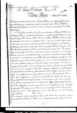
Mar. 13, 1834
Schrieel A. Astell, Geneva N.Y.
Letters Patent March 13, 1834.
The Schedule referred to in these Letters Patent and making part of the same containing a description in the words of the said Schrieel A. Astell himself of his improvement in the mode and manner of making "Horse Power Machines."
To all persons to whom these presents shall come, Schrieel A. Astell of the Village of Geneva, in the County of Ontario and State of New York, mechanic, greeting. Be it known that I the said Schrieel A. Astell have invented, constructed and made and applied to use a new and useful improvement in the mode and manner of making Horse Power Machines to be attached to threshing Machines or any other Machinery called "Astell's Cast-Iron Horse Power," the whole of the same to be made of wrought or cast iron. The advantage of having the Horse Power and machinery made of iron is its being stronger, more durable, less liable to go out of order and repair, more steady and regular in its operation and all the of greater strength and power, it is of less size, more compact, takes up less room, and is more easily transported from place to place, if required, the advantages above recited, the simple compact of the machine, the durability of its material, the facility with which it can be moved and put in operation, its great strength and the low price for which it can be obtained gives the said Horse Power a decided advantage and superiority over any other now in use. The draft of the Horse Power here attached and described as Plates Nos. 1, 2, 3, 4, the following thereof together with the specification and description of the same as given below particularly set forth and describe the different parts of the machine, the distinct operation and use of each part and the effect produced in being put in operation. The improvement claimed is in making the Horse Power of iron instead of wood or other materials and in the manner in which the same is put together.
Wate & 10.1
By an upright right, right hand view of the Horse Power Machine is shown and described as follows: Plates, or an upright view of the shaft to which
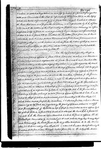
Page 3.
to which is attached Cog Wheel c.c. and f.f. by means of a plate or flange c.c. with and Connected to the Shaft as represented by 33 in Plate No. 4. On the top of which is a Collar represented by j.j. in Plates Nos. 1 and 2 to which is attached the levers h.h. to move and propel the Machine and represented by h.h. in Plates Nos. 1 and 2. The bottom of the Shaft resting on Plate b.b. and coming on a point supported at top by Plate c.c. and regulated by keys or ridges as represented by letters r.r.r. in Plate No. 4. Section 44. The bottom plate from one to two inches thick and 10 inches wider than the bottom said plate made permanent and supporting Shaft a. at the bottom in which plate the bottom of Shaft a. rests or moves on a point when in operation. Said bottom plate being made fast to the foundation as represented by letter e.
cc. The top plate supporting Shaft a. which more plainly appears in Plate No. 2. Letters cc. in which is a ball or friction wheel which is represented in Plates No. 1 and 2 and marked letter i. which rolling on the upper edge of Cog Wheel c.c. and f.f. regulates the meshing of the Cogs of the Main Wheel into the cogs of pinion Wheel f. and the upright posts connecting plate b.b. with plate c.c. as more plainly appear in Plate No. 8 letters a.a. e. The foundation on which the Machine is placed f. the pinion wheel meshing into main wheel c.c. and f.f. on the Shaft of which is Spur Wheel g.g. as represented by said letter g. in Plates No. 1, 2 and 3. g.g. the Spur Wheel as before mentioned attached to the Shaft of pinion Wheel f. and meshing into pinion Wheel h. as represented by letter h. in Plates No. 1, 2, 3. h. the pinion wheel meshing into Spur Wheel g. as more plainly appear in Plate No. 3. Letter h on the end of the Shaft of which is a universal joint connecting with line Shaft l.l. which when moved propels the Machine. i. a small friction wheel or trammel running on top plate cc. regulating the gearing of main wheel c.c. and f.f. into pinion wheel f. j.j. the Collar on top of Shaft a. connected as more appears by the top of Shaft letter a. in Plate No. 2 to which is attached the levers h.h. in Plates No. 1 and 2. h.h. the levers as before described to which the power is applied. l.l. the line Shaft connected by universal joint and which may lay in any angle and connecting the horse power with any other Machine. m.m. the universal joint connecting line Shaft l.l. a.a. m.m. ball heads or nuts fastening the Machine to its foundation through bottom plate b.b. c.c. the body of the main
Page 4.
where it will more plainly appear in plates No 2 and 4, and which though cast whole or in segments or either attached to the shaft, or separate or cast in segments its description will plainly appear by lines yyy yyy yyy in plate No 4. Letters f.f. the Cog wheel cast whole or in segments and attached to the body of the main wheel, c.c. by bolts or screws and nuts, g. Coupling or key in which line of hoop runs in the Cope or groove Confining the Shaft of the Machine to the body or place in which it must be represented by letters r.r. in plate No 2.
Plate No 2
A horizontal view of the top part of the Machine. Letters a. the top of main Shaft c.c. the top plate, d.d.d.d. Mortises for the uprights or posts as represented by letters a.d. in plate No 1. g. the Spur wheel as more plainly appears by letters g.g. in plate No 3. h. the pinion wheel as will also appear by letter h. in plate No 3. i. the Mortise in top plate c. in which the traveller or friction wheel runs. j.j.j.j. the Collar on top of Shaft a, on which rest the levers k.k.k.k. k.k.k.k. the levers fastened to Collar j.j.j.j. by bolts or screws as represented by square dots. l. the end of line Shaft, in the universal joint o the body plate of the main wheel cast whole or in segments. n.n.n. the Cope or groove Confining the Shaft to place
Plate No 3
An upright end view of the Horse Power and Machine. Letters b. the bottom plate, c. the top plate, d.d. the upright posts or pillars, g.g. the Spur wheel meshing into pinion wheel h. h. the pinion wheel.
Plate No 4
A horizontal view of the top of the main Cog wheel. Letters a. represents the manner in which the main Shaft a. in plate No 1 passes through the top plate c.c. in plate No 2 and regulated by keys and wedges, as represented by letters s.s.s.s. c.c.c.c. the body plate of the main wheel cast whole or in segments the segments or divisions being represented by lines y.y.y.y.y. b.b.b. the flange or plate cast solid with main Shaft a. Plate No 1 to which the body of the main wheel is attached by bolts as represented by square dots. The circle lettered line represents the bottom edge of the flange under the main wheel. Line represents the rabbet in the flange in which receives the body of the main wheel. Letters t.t.t.t.t. open spaces in the form of a heart or other shape there by saving metal and lessening the weights of the wheel, t.t.t. keys or wedges
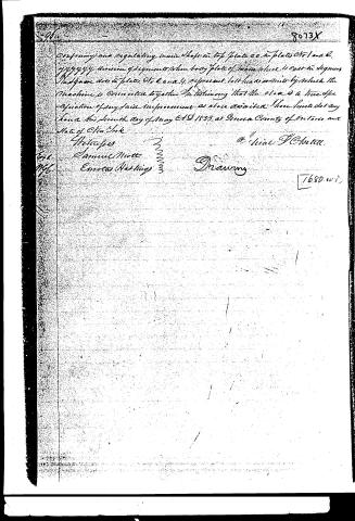
Page 5.
Confirming and regulating mine shafts in top plate cc in plates No 1 and 2.
yyyyy division of segments when top plate of mine wheel is cast in segments
And those dots in plates No 2 and 4 represent bolt heads or nuts by which the machine is connected together. In testifying that the above is a true specification of my said improvement as above described. In presence of my hand this 12th day of May A.D. 1833 at Geneva County of Ontario and State of New York.
Witnesses
Samuel Mott
Emmett Hastings
Drawing
1680 w i
Published accounts: journal notice
Notice in the monthly list of patents, with remarks
Journal of the Franklin Institute, new ser., vol. 14 (1834), p. 243 · View the page
38. For a Horse Power; Jehial F. Axtell, Geneva, Ontario county, New York, March 13.
Remarks. "The improvement claimed is in making the horse power of iron instead of wood or other materials, and for the manner in which the same is put together."-As there are many horse powers made of iron, this claim is good for nothing; and even had such not been the case, the making it of iron, without any novelty in its principle, would not be found to be that kind of improvement which the law requires; as to the manner of putting it together, there is nothing specified as new or peculiar, and nothing with which every workman is not familiar.
About this record
- Patentee
- DATAMP
- Date
- the Name and Date index of patents, DATAMP, USPTO records
- Invention
- DATAMP
- Listed in
- the Name and Date index of patents, DATAMP, USPTO records, Jim Shaw's X-patent list, the Journal of the Franklin Institute, Burke's List of Patents (1847)
- Burke's 1847 Patent Office list gives the same patent.