

Drawings and documents
National Archives restored drawings: drawing
Calvin Page's Patent Drawing for a Corn Sheller

National Archives, Restored Patent Drawings (Record Group 241) · Full-size scan at the National Archives · Catalog record
Show the text on the drawing Hide (117 words)
Words on the drawing as machine-read by the National Archives; not checked. Useful mainly for searching.
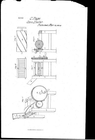
0. I / 130. THRASHING. / [59] C / Corn Shellers. / Catvin Paor a Braylo / Vollip.269. / Breast and Cylinder. / P4- / born Heller, / Patented 13 March 1834, / CLASSI ICATION / 8076-+ / DIVISION. / Filf 4 / Fid 5 / Fig.1. / MJ / Fif.2. / Al / Fif.3. / D, / IN / I.H. / DB / References, Fig.1. sometrical projution, Figid. front view, Fig 3, virtical section, / Patel Office Deary this 41 / Eig.4.virtical rack, Fif.5, cylinder. A frame, B, cylinder, C, far on which com rests, / Destrical rack, Ensprings. Escrews. Ghopper, H, coofwhed. I.pinon, Kerauk, / Made muder the education of the Commission of Patents / in conformity with act of leongrep 3. March 1837 / It L Ясполь / (move not ni Office 22 Jam Jenelice 55 / Comminprom of Patients
USPTO scan
The patent as scanned by the USPTO
-
 Page 1
-
 Page 2
-
 Page 3


U.S. Patent and Trademark Office · Google Patents
Show the transcription Hide (915 words)
Machine transcription (LightOnOCR) of the pages as scanned by the USPTO, most of them the handwritten copies made when the records were restored after the 1836 fire. Not checked; it can misread handwriting, so compare it with the scan.
Page 1.
8076X
C. Page.
Corn Sheller.
Patented Mar. 13, 1834.
THE NORRIS PETERS CO., WASHINGTON, D.C.
Page 2.
80764 Mar. 13, 1834
Calvin Page of Sanbornton, New Hampshire
Letters Patent
The Shackle referred to in the Letters Patent and making part of the same containing a description in the words of the said Calvin Page himself of his improvement in the machine for shelling Corn.
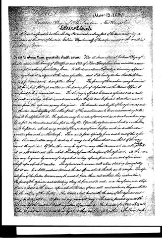
To all to whom these presents shall come. I, the undersigned, Calvin Page of Sanbornton in the County of Strafford and State of New Hampshire, have invented a new and useful machine for shelling Corn, to which machine I attach a winning apparatus by which it is operated at the same operation, and I do hereby declare that the following is a full and exact description thereof — The frame of the machine may be varied in its form, but that represented in the drawing thereof deposited in the Patent Office, I have found to be a convenient one. The shelling is effected between a cylinder and a vertical rack or gearing which is made movable so that it can be forced close to, or made to recede from, the cylinder as may be required. The diameter and length of the cylinder as well as the size and length of the other parts of the machine are to be varied according to the force to be applied to it. The cylinder may be made of iron, and in a small machine may be a foot in diameter and two feet in length. Upon this cylinder iron beaters or shellers are to be placed, which may consist of bars or rods of iron half an inch in width and a quarter of an inch in thickness. These are to pass spirally from end to end of the cylinder. Their inclination may be such as to carry each of them about one third of the way round the cylinder. Of these there may be eight or any other convenient number, firmly attached so as to stand out their whole thickness from the surface of the cylinder. To this motion may be given by means of a cog wheel acting upon a pinion on one end of an iron shaft upon which it revolves. The cylinder will answer well when standing horizontally but it may be a little inclined towards the end from which the cobs are to escape. The special form of the beaters however may be made to force them out without this inclination. The front of the cylinder and extending along it from end to end, is a bar of iron or a slide of wood faced with iron, upon which the ears of corn rest, and revolves as they are shelled by the action of the beaters. This slides about but with the axis of the cylinder and may be supported in its place in any convenient way. The corn is pressed against the cylinder by the vertical rack or gearing before named. This consists of vertical slats attached at each end to a iron frame by which they are joined together. The corn crops—
Page 3.
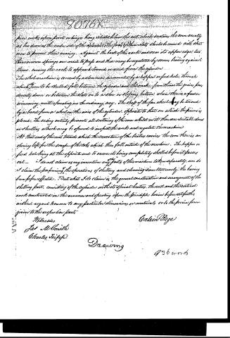
pieces works upon parts or binges being situated below the exit which sustains the corn usually as low down as the under side of the cylinder. The face of this plate should be curved with shut iron to prevent their wearing. Against the back of this rack and near its upper edge, two thin iron or iron springs are made to press and this may be regulated by screws bearing against them, causing the rack to approach towards or recede from the cylinder.
This whole machine is covered by a cover and supported by a hopper or feed hole, through which the corn to be shelled falls between the cylinder and the rack. From thence the grains pass directly down or between the slots on to a shoe or sloping bottom, where there is a fan or winnowing mill operating in the ordinary way. The shaft of this fan wheel may be turned by a band from a wheel on the axis of the cylinder, opposite to that on which the pins are placed. The casing entirely prevents all scattering of the corn whilst in it. There are suitable doors or shutters which may be opened to inspect the work and regulate the machine.
At that end of the rack towards which the curvature of the beater carries the corn there is an opening left for the escape of the cobs which thus fall outside of the machine. The hopper or feed hole being at the opposite end to ensure its being completely shelled before it passes out.
I do not claim as any invention any parts of this machine taken separately, nor do I claim the performing the operations of shelling and cleaning simultaneously, this having been before effected. But what I do claim is the general construction and arrangement of the shelling part, consisting of the cylinder with its spiral beater, the rack and the vertical rack constructed in the manner and operating upon the principles herein before set forth; without regard however to any particular dimensions or materials, or to the precise form given to the respective parts.
Witnesses
Jas M. Smith
Charles Tripp
Calvin Page
Drawing
436 words
Published accounts: specification
Specification printed in the Journal of the Franklin Institute
Journal of the Franklin Institute, new ser., vol. 14 (1834), p. 199 · View the page
Text of the specification as printed in the Journal, from OCR; not proofread.
Specification of a patent for a Machine for Shelling Corn, &c. Granted to CALVIN PAGE, Sandbornton, Strafford county, New Hampshire, March 13, 1834. To all to whom these presents shall come, be it known, that I, Calvin Page, of Sandbornton, in the county of Strafford, and state of New Hampshire, have invented a new and useful machine for shelling corn, to which machine I attach also a winnowing apparatus, by which it is cleaned at the same operation; and I do hereby declare that the following is a full and exact description thereof. The frame of the machine may be varied in its form, but that represented in the drawing thereof deposited in the patent office, I have found to be a convenient one. The shelling is effected between a cylinder and a vertical rack, or grating, which is made movable, so that it can be pressed closer to, or made to recede from, the cylinder, as may be required. The diameter and length of the cylinder, as well as the size of the other parts of the machine, are to be varied according to the power to be applied to it. The cylinder may be made of wood, and in a small machine may be a foot in diameter, and two feet in length. Upon this cylinder iron beaters or shellers are to be placed, which may consist of bars, or rods, of iron, half an inch in width, and a quarter of an inch in thickness; these are to pass spirally from end to end of the cylinder, their inclination may be such as to carry each of them about one-third of the way round the cylinder; of these there may be eight, or any other convenient number, firmly attached, so as to stand out their whole thickness from the surface of the cylinder. Motion may be given to this by means of a cog wheel acting upon a pinion on one end of an iron shaft upon which it revolves. The cylinder will answer well when standing horizontally, but it may be a little inclined towards the end from which the cobs are to escape; the spiral form of the beaters, however, may be made to force them out without this inclination. In front of the cylinder, and extending along it from end to end, is a bar of iron, or a strip of wood faced with iron, upon which the ears of corn rest, and revolve, as they are shelled by the action of the beaters. This stands about level with the axis of the cylinder, and may be supported in its place in any convenient way. The corn is SPOOR'S Stoves for Anthracite. pressed against the cylinder by the vertical rack or grating, before named. This consists of vertical slats, attached at each end to a cross piece, by which they are framed together. The lower cross piece works upon pivots, or hinges, being situated below the rest which sustains the corn, usually as low down as the under side of the cylinder. The faces of these slots should be covered with sheet iron to prevent their wearing. Against the back of this rack, and near its upper edge, two, three, or more, springs are made to press, and these may be regulated by screws bearing against them, causing the rack to approach towards, or recede from, the cylinder. The whole machine is covered with a close case, surmounted by a hopper, or feed hole, through which the corn to be shelled falls between the cylinder and the rack; from thence the grains pass directly down, or between the slats, on to a shoe or sloping bottom, where there is a fan, or winnowing mill, operating in the ordinary way. The shaft of the fan wheel may be turned by a band from a whirl on the axis of the cylinder opposite to that on which the pinion is placed. The casing entirely prevents all scattering of the corn, whilst there are suitable doors, or shutters in it, which may be opened to inspect the work, and regulate the machine. At that end of the rest towards which the curvature of the beaters carries the corn, there is an opening left for the escape of the cobs, which thus fall outside of the machine; the hopper, or feed hole, being at the opposite end, to insure its being completely shelled before it passes out. I do not claim as my invention any of the parts of this machine, taken separately, nor do I claim the performing of the operation of shelling and cleaning simultaneously, this having been before effected; but what I do claim is the general construction and arrangement of the shelling part, consisting of the cylinder with its spiral beaters, the rest, and the vertical rack, constructed in the manner, and operating upon the principle hereinbefore set forth; without regard however, to any particular dimension, or materials, or to the precise form given to the respective parts. CALVIN PAGE. Description of " an improvement in Stoves for Burning Anthracite or other Fuel." Patented by ABRAHAM E. SPOOR, Coxsackie, Greene county, New York, March 15, 1834. The form of the stove esteemed the best by the patentee, is that of a cubical box. It has two openings in front, one for the ash pit drawer, and the other a door for the supply of fuel, about nine inches above the former. The door is to be an open frame containing mica, and its lower edge is to be level with the top of the fire, so that its whole surface may be exposed to view. Another opening is to be made either in the front or back, upon a level with the grate, for the purpose 1 SPOOR'S Stoves for Anthracite. of introducing a shaker, to remove the ashes; a longitudinal stopper is made to close this opening very perfectly. On each side of the ash drawer are two vertical plates, leading from front to back, and dividing this lower part of the stove into three compartments, the two exterior of which are to form a portion of the flues. These plates sustain a horizontal one, which has the circular grate in its centre; this horizontal plate has its four corners removed to make openings into the compartments on each side of the ash drawer. The circular grate is detached from the horizontal plate upon which it rests, and is capable of being vibrated circularly, or of being tilted to discharge the fuel, when moved round to a certain point. The holes in the corners of the lower plate are surrounded by vertical plates forming them into four flues; the two in front may extend two or three inches only above the top of the furnace, but the two in the rear are extended up to a sloping back, or to the top plate of the stove, and be surmounted by pipes. At about nine inches above the horizontal plate is a second, similar to it, with a round hole in its centre; this forms the top of the furnace, the space between the two plates being filled with fire brick. Above the furnace there is a sloping back plate cutting off a triangular prism at the back of the stove, and forming a chamber into which the rear flues may enter, and from which the smoke pipe of the stove leads. The patentee claims as improvements, "the grate above described, with the mechanism for supporting it, and also the enclosed avenue for the shakers." "The internal revolving flues within the body of the stove, by which the heated air directly from the glowing mass of burning coal, in its revolution, first downward, then backward, and upwards, is brought in contact with nearly the whole internal surface of the outside plates of the stove, imparting heat to the room, and furnishing an opportunity for warming the feet." "Another improvement relates to the form of the burning mass; it is founded on the fact that anthracite does not burn so well in a square, or angular, as in a cylindrical form; and that when a mass of coal over nine inches in height becomes all ignited at once, so many ashes are formed and diffused through the mass, that it is impossible to separate the ashes effectually from the coal, without introducing the poker, and stirring it up from the bottom." "The mass of coal should be in the form of a cylinder, and in no case, whatever be the size of the stove, exceed in height eight, or at most, nine inches." "I claim as an improvement the location of the transparent door, at such an elevation as to expose the whole surface of the fire to full view." The validity of the last claim we are constrained to doubt, as the location spoken of is that of cylindrical stoves for anthracite, in general; its location is not new, therefore, nor is it pretended that the door itself is so. Can the patentee prevent me from putting a transparent door, an old contrivance, on to a stove which I have had in use for years, in the place of the old door; we rather think not. The improvement in this stove which "relates to the form of the burning mass," is not absolutely claimed, nor do we perceive with what propriVOL. XIV. No. 3.- SEPTEMBER, 1834. 26 CRUMBER'S Stave Dresser. ety it can be alluded to as appertaining any more to this stove than to thousands of others which have been in use ever since the general introduction of anthracite. The patentee will find but few in which it has been attempted to exceed the height of nine inches in the burning column. The arrangement of the flues appears to be good, and sufficiently distinct to sustain the claim made to this particular construction.
Published accounts: journal notice
Notice in the monthly list of patents, with remarks
Journal of the Franklin Institute, new ser., vol. 14 (1834), p. 243 · View the page
39. For a Machine for Shelling Corn; Calvin Page, Sandbornton, Strafford county, New Hampshire, March 13.
Remarks. (See the specification.)
About this record
- Patentee
- DATAMP
- Date
- DATAMP, USPTO records, Burke's List of Patents (1847)
- Invention
- DATAMP
- Listed in
- the Name and Date index of patents, DATAMP, USPTO records, Jim Shaw's X-patent list, the Journal of the Franklin Institute, Burke's List of Patents (1847)
- The sources give different dates; the date shown is the one most of them agree on.
- The Franklin Institute's journal confirms the date shown.
- Burke's 1847 Patent Office list gives the same patent.