

Drawings and documents
National Archives restored drawings: drawing
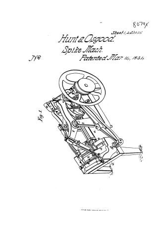
Hunt and Osgood's Patent Drawing for a Spike Machine


National Archives, Restored Patent Drawings (Record Group 241) · Full-size scan at the National Archives · Catalog record
Show the text on the drawing Hide (99 words)
Words on the drawing as machine-read by the National Archives; not checked. Useful mainly for searching.
Sheet 1. RE78 / 8079 / VISION / Coming & Horner apigness of oran / Homt and osgood / HUNT & OSCOOD'S / march 83/- / Patented 14March. 1834. and / SPIKE MACHINE. 0 / Reissued Jan Jan 15 15 1846 / Respond / Fig. 2 / Fig 3 / II / olA
Sheet 2. 85. METAL WORKING, / Spike Making. / (2Sheets) Sheet I / $5 / CLASSIFICATION / Re 78 / Hunt & Osgood / DIVISION. / NOLL 8079 CLASSING / DIVISION. / Spike Machine / Patented Mar.14th1834 / No 78 / Reissued Jan. 15th 1846 / Fig / III / 495 / 695
Sheet 3. Hunt & Osgood / Spike Machine / 8079- / CLASSIFICATION / Patented Mar.14 / Re 78 / Reissued Jan. 15th 1846 / DIVISION. / d' / OI / at's / 's / 2° / Fig.2 / S" / 1° / Fig. 3
USPTO scan
The patent as scanned by the USPTO
-
 Page 1
-
 Page 2
-
 Page 3
-
 Page 4
-
 Page 5
-
 Page 6
-
 Page 7
-
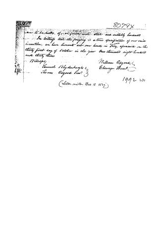 Page 8


U.S. Patent and Trademark Office · Google Patents
Show the transcription Hide (1,978 words)
Machine transcription (LightOnOCR) of the pages as scanned by the USPTO, most of them the handwritten copies made when the records were restored after the 1836 fire. Not checked; it can misread handwriting, so compare it with the scan.
Page 1.
8079X
Sheet 1, 2, 572355
Hunt & Osgood.
Spike Mach.
Patented Mar. 14, 1834
No.
Fig. 1.
N. PETERSON, PHOTO-LITHOGRAPHER, WASHINGTON, D.C.
Page 2.
80791
Sheet 2, 2 Sheets.
Hunt & Osgood
Spike Mach.
No. Patented Mar. 14, 1834.
Fig. 2.
Fig. 3.
W. PETERS, PHOTO-LITHOGRAPHER, WASHINGTON, D.C.
Page 3.
8079 X
Jan. 14, 1834. No. 12
457.
William Osgood & Ebenezer Hunt of Troy, N.Y.
Letters Patent
The schedule referred to in these Letters Patent and making part of the same, containing a description in the words of the said William Osgood & Ebenezer Hunt, themselves of their improvement in the machine for making wrought iron spikes and nails —
To all persons to whom these presents shall come,
Be it known that Ebenezer Hunt and William Osgood, both of Troy in the county of Rensselaer, and State of New York, have invented a Machine for making wrought nails and spikes, a true and accurate description of which is as follows:
The nails are to be manufactured from rods, either rolled or slit but rolled rods are preferable, and the size of the rod must correspond with the size of the body of the nail. The points of the nails may be either flat or sharp but flat points are made most advantageously by our machine. The nail rod is put into the machine hot & the piece to form the nail is cut off, and gripped and immediately after is pointed and heated both at the same time.
The form of the machine may be so varied in its details that no description can be given which will comprehend all the varieties of which it is susceptible, but it is the mode of operation which we claim as forming the ground-work of this invention which several operations are as follows:
First cutting off the piece of rod for the nail and gripping it, second, the hammering and thereby forming the point, third the heating which has been performed as above stated, at the same time; fourth the disengaging the nail & opening, to receive the use for the next nail or spike.
The foundation or base plate of the machine is a strong plate.
Drawings see Appendix No. 1045
Page 4.
8079X
a piece of cast iron of such shape and with such upward and downward projections as to accommodate the operating part, hereinafter to be specified.
The apparatus for performing the first operation viz. cutting off and gripping, consists of two compound blocks one of which is fixed and the other moveable. The fixed or stationary blocks consists of three plates placed horizontally one upon the other, the two lower plates are of a width exactly equal to the length of the body of the nail. The thickness of the bottom one is unessential, say from three fourths of an inch to one inch and a half; The middle plate must exactly correspond in thickness with the size of the body of the nail, and must be made of steel or of wrought iron with steel on the inner side or of some other substance equally hard. The inner side of the middle plate forms one side of the cavity in which the nail is held for heading and pointing. The third or top plate of the fixed block is wider and longer than the other two, and the end which projects over the middle plate forms the upper side of the square cavity in which the nail is gripped. The moveable or sliding block, which we denominate the die box is a piece of cast iron consisting of three sides of a square with a bottom, which bottom is a little, say one fourth of an inch lower than the bottom of the bottom plate of the fixed block. The cavity of the sliding block or die box is occupied by two plates, the bottom one of which is in two pieces lengthwise which are not fastened but placed side by side. The width of the widest piece corresponds with the length of the body of the nail, and that of the narrowest piece, with the taper or point of the nail which is about one third the width of the widest piece. The widest of these pieces, projecting under the middle plate and fitting closely to it, forms the bottom of the cavity which grips the body of the nail. The narrow pieces also projecting under, forms the bed on which the point of the nail is hammered, and the top of this last
Page 5.
8079X
mentioned piece is shaped by grinding or otherwise, so as to fit the angle of the point of the nail or spike.
On the compound plate, last specified, lies another plate of the same width as the widest piece of the plate under it, which plate is about an inch more or less in thickness, but the inner end, say about one inch of its length is reduced to the exact thickness of the middle plate opposite; and when the die box is forced inwards, and when the said bed plate passes under the opposite middle plate, the bed plate, the middle plate, and the thin end of the plate last specified form three sides of the cavity or chamber in which the nail is gripped. The third or top plate of the fixed block, passing over the end of the top plate of the die box, also forms the upper or fourth side of the grip, — so the die box is forced inwards to grip the nail; the forward end of it is raised just before it stops, by a little inclined plane, in order to grip the nail on each of its four sides. On the front end of the main bed plate, is the cutter block, made fast at the outer end to said bed plate, in a place made to receive it and is held secure by a dovetail wedge, the inner or operating end of said cutter block, is exactly where the rod is cut off at the point of the nail.
When the rod is thrust in, to form the nail, the further end which is to form the head strikes against a spring the opposite end of which is fastened to the bed plate, and the cutter which is attached to, and moves with the die box coming against the cutter block, the piece which is to form the nail is thereby cut off, and gripped and is ready to form the head and point.
When the nail is thus cut off, it is carried forward by the die box until the back end which is to form the head, passes by, and is clear of the gage spring above mentioned and the front end which is to make the point is just past but soon with the back edge of the cutter block, and at
Page 6.
8079x
The instant—commencing the operation of heading and pointing.
The header is a solid bar of cast or wrought iron or other proper substance, say from eighteen inches to two feet in length and from three to four inches square, lying horizontally and lengthwise of the machine on proper sliding beds or beds, so that the header die which is inserted in the forward end of the header, may be exactly against the perfecting anvil, which is to form the head of the nail, and strong lever of cast or wrought iron is bent nearly at right angles, but with one end or arm longer than the other. The short arm of this lever, which at its end, forms the fulcrum, is connected by a strong movable or articulating joint, to two downward projections from the underside of the bed plate, and the other or longer end of said lever rests upon a cam on the main shaft which lies across the back end of said bed plate, while the angular joint or elbow stands against the back end of the header, and the end of said lever being raised by said cam, the header with its die forms the head of the nail, and when so formed the header is carried back by a spring.
The point is formed by two set hammers, each hammer being operated by a lever in the following manner. The left hammer stands in an angle with the nail of about forty-five degrees, so that when it strikes the nail, the stroke corresponds with the extension of the nail forward. The upper end of this set hammer is connected by a knee joint to a strong lever, which lever rests at about one third of its length on two fulcrum posts, strongly attached to the bed plate, and the opposite or longer end of which lever rests on the periphery of a wheel, with four, more or less rolling arms, or projections on its edge, which give as many successive strokes to the point of the nail, as the edge of this cam wheel is so adjusted as to advance the hammer a little at each successive stroke, as the point of
Page 7.
8079x 455
the nail diminishes, the end of this hammer projects and opens through a space left for that purpose in the top plate above specified. The side hammer lies horizontally in such a situation as to strike against the side of the point of the nail, but strikes it at right angles with the nail, and the lever which operates it lying in the bed plate, has for its fulcrum a pin standing on the same, and receives its motion from a roller cam, or undulation, on the side of the cam wheel last above specified.
The die box is sliding block, above specified, is driven onward to grip the nail, by a wedge operating horizontally behind the outer end of it, which wedge is driven forward by the angular-point or elbow of a lever, like the one above specified, but acting in a contrary direction and the cam which moves it, is on the end of the main shaft, in shape nearly semi circular and so adjusted as to perform its operation in about half the time of each revolution; leaving the remaining half of the time to reset the rod for the next nail. The die box, like the header, is carried back by a spring, and as the die box comes back and the grip is opened the above mentioned gauge spring serves, when necessary to disengage the nail and in case it should fail, it is aided by a hook, which is attached to the die box and drawing back with it against the head of the nail disengages it, if not done before.
We have sometimes used especially in making square pointed nails, what we term a forcing slide, which is a small instrument operating by the side of the cutter block, in such manner that when the piece for the nail is cut off, this forcing slide operating by lever and a proper cam & press the piece back, so as to leave room for the point to remain clear of the cutter block, and when this is done the gauge spring may be dispensed with. All the operating parts of the gripping, heading, and cutting apparatus which require it are.
Page 8.
8079x
are to be made of, or faced with steel and suitably hardened.
In witness that the foregoing is a true specification of our said invention, we have hereunto set our hands in Troy, aforesaid on the thirty first day of October in the year One thousand eight hundred and thirty three.
Witnesses:
Samuel Blydenburgh & Thomas Osgood Jr.
William Osgood, Ebenezer Hunt.
1992 207
(Letter written Dec 18 0839.)
Published accounts: journal notice
Notice in the monthly list of patents, with remarks
Journal of the Franklin Institute, new ser., vol. 14 (1834), p. 244 · View the page
42. For a Machine for Making Wrought Nails and Spikes; William Osgood, and Ebenezer Hunt, city of Troy, Renselaer county, New York, March 14.
Remarks. In this machine the nails are to be made from rolled or slit rods of the proper size for the body of the nail. The nail rod is to be put into the machine while hot, and the piece to form the nail is cut off, griped, pointed, and headed, at one operation. The patentees observe that the form of the machine may be so varied, that no description could comprehend all these variations, and that their claim is not therefore to the form, but to the modes of operation. The specification is carefully drawn up, and there is a good perspective representation of the machine, but still we think it defective in matters of detail, which can rarely be shown in a single perspective drawing. Those "modes of operation" upon which the patentees rely, are not at all set forth, but left to be inferred from the general description. Were it otherwise, we could not pretend, without adequate engravings, to present them to the reader, and shall not now make any attempt so to do.
About this record
- Patentee
- DATAMP
- Date
- the Name and Date index of patents, DATAMP, USPTO records
- Invention
- DATAMP
- Listed in
- the Name and Date index of patents, DATAMP, USPTO records, Jim Shaw's X-patent list, the Journal of the Franklin Institute, Burke's List of Patents (1847)
- Burke's 1847 Patent Office list gives the same patent.