

Drawings and documents
National Archives restored drawings: drawing
Jacob V.A. Wemple's Patent Drawing for a Thrashing Machine Using Horse Power

National Archives, Restored Patent Drawings (Record Group 241) · Full-size scan at the National Archives · Catalog record
Show the text on the drawing Hide (51 words)
Words on the drawing as machine-read by the National Archives; not checked. Useful mainly for searching.
Motors; / JACOB V.A. WEMPLE / -power is Clears. / p3 / Threshing Machineg; Horse Power. / classification / Pateniod elba- / 8106-X / DIVISION. / Bat mar, 25-1834 / Hig. 2. / Sig: I / p. / W. / p. / Fig 5 / y/o / Hisso / Hights / Fig.7 / Hig:6 / yig.8
USPTO scan
The patent as scanned by the USPTO
-
 Page 1
-
 Page 2
-
 Page 3
-
 Page 4


U.S. Patent and Trademark Office · Google Patents
Show the transcription Hide (1,611 words)
Machine transcription (LightOnOCR) of the pages as scanned by the USPTO, most of them the handwritten copies made when the records were restored after the 1836 fire. Not checked; it can misread handwriting, so compare it with the scan.
Page 1.
8106X
J. V. A. Wemple,
Horse Power.
Patented Mar. 25, 1834.
Page 2.
8106X
Mar. 25, 1894
Jacob V. A. Wemple, of Florida, N. York.
Letters Patent
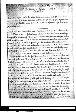
The schedule referred to in these Letters Patent, and making part of the same, containing a description in the words of the said Jacob V. A. Wemple himself of his improvement in the machine for threshing grain & also in the construction & formation of a horse power for propelling said machine.
To all to whom these presents shall come: Be it known that I Jacob V. A. Wemple of the Town of Florida in the _ of Montgomery State of New York have invented a new & useful improvement in a machine for threshing grain - And the horse power operating said machine which horse power may be applied to all other uses & purposes to which horse power usually is or may be applied - and that the following is a full description of the construction & operation of said machine & horse power as invented or improved by me - The machine is constructed with a frame four feet long two feet ten inches wide & two feet two inches high made with four posts three inches thick & six inches wide two plates three inches thick & nine inches wide, two skillets three inches square - three girts or cross timbers three inches square - A circular or concave bed two feet & four inches long which is to be made of hard wood plank eight inches wide & three & a half inches thick faced with sheet iron & tenoned into the plates or may be set on spiral springs & a cylinder of solid hard wood two feet three & a half inches long & nine inches in diameter or larger if thought proper bound with sheet iron, with an iron shaft running thro' the center of it an inch & a quarter square with a bed ring at each end of the cylinder; one end of the shaft projecting far enough to receive or whin of about five inches diameter - The ends of the cylinder are secured with iron bands - The cylinder is to run in cast iron boxes counter sunk in the center about three fourths of an inch & filled up with gink for the bedrings - The boxes are in two pieces confined to the plates by means of iron bolts - In the upper half of the box is a reservoir with a small hole thro' from the bottom of it to the shaft to contain oil for oiling the bearings - The teeth in the concave are an inch & a half long to the first shoulder, an inch wide at the shoulder & half an inch at the end three eighths of an inch thick at the shoulder & one fourth of an inch at the end & the edge opposite the shoulder being the part which strikes the grain should be rounded to prevent its cutting the grain - The flank of the teeth is four inches in length two inches of which is only one fourth of an
Page 3.
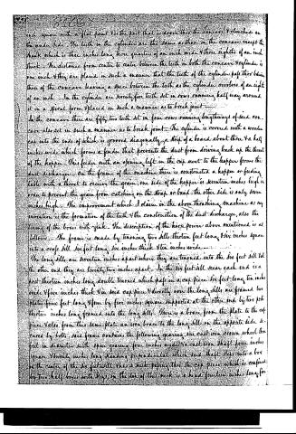
inch square with a flat point. Yet the part that is drawn thro the concave & clenched on the under side. The teeth in the cylinder are the same as those in the concave except the flank which is three inches long three quarters of an inch wide & three eighths of an inch thick. The distance from center to center between the teeth in both the concave & cylinder is one inch & they are placed in such a manner that the teeth of the cylinder pass thro' below those of the concave leaving a space between the teeth as the cylinder revolves of an eight of an inch. In the cylinder are seventy-five teeth set in rows running half way around it in a spiral form & placed in such a manner as to break joint.
In the concave there are fifty-two teeth set in four rows running lengthways of said concave also set in such a manner as to break joint. The cylinder is covered with a wooden cap into the ends of which is grooved diagonally a strip of a board about three & a half inches wide which forms a feeder that prevents the dust from driving back up the throat of the hopper. This feeder with an opening left in the cap next to the hopper forms the dust discharger. On the frame of the machine there is constructed a hopper or feeding table with a throat to receive the grain, one side of the hopper is seventeen inches high in order to prevent the grain from catching on the strap or band; the other side is only seven inches high. The improvement which I claim in the above threshing machine as my invention is the formation of the teeth & the construction of the dust discharger, also the lining of the boxes with zinc. The description of the horse power above mentioned is as follows. The frame is made by tenoning two sills thirteen feet long & six inches square into a cross sill six feet long, six inches thick & ten inches wide.
The long sills are seventeen inches apart where they are tenoned into the six feet sill & at the other end they are twenty-two inches apart. In the six feet sill near each end is a post thirteen inches long double tenoned which passes in a cap piece six feet long ten inches wide & five inches thick. In said cap piece & directly over the long sills are framed two plates four feet long & four by five inches square supported at the other end by two posts thirteen inches long framed into the long sills. There is a brace from the plate to the cap piece & also from this same plate an iron brace to the long sill on the opposite side secured by bolts. Said frame contains the following gearing, one cast iron crown wheel three feet in diameter with spur gearing four inches wide & a cast iron shaft four inches square & twenty inches long standing perpendicular which said shaft steps into a box in the center of the six feet sill. There is a neck passing thro' the cap piece which is confined by two half boxes with keys on the top of this neck is a head fourteen inches long for
Page 4.
81067
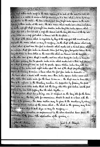
under high & three inches across in the center tapering to an inch at the ends & in each end of the head is a notch to receive a bolt for securing on it a lever which is let on by means of a mortise in the center. The lever is twenty feet long & eight inches square in the center tapering to three inches at the ends. The said crown wheel makes into a seven inch pinion on another upright shaft of wrought iron seventeen inches long & two inches square, which shaft steps into a box let into a cross sill tenoned into the long sills & runs at the top into a box bolted on a cross girt which is tenoned into the two plates.
The shaft of the pinion wheel is regulated by keys to the cross girt & sill so as to mesh in vent with the crown wheel as may be necessary. On the shaft of the pinion wheel is also a bevel wheel of cast iron two feet in diameter which meshes into a six inch pinion wheel on a wooden shaft five inches in diameter & nine feet long lying horizontal between the two long sills & runs in boxes bolted on the cross sills which are tenoned into the long sills. On the other end of said shaft is another cast iron wheel twenty-two inches in diameter with spur gearing two & a quarter inches wide which meshes into a three inch pinion on a shaft of wrought iron an inch & a quarter square & sixteen inches long with two bearings of two inches each eight inches apart the end of the shaft projecting four inches beyond the bearing to receive a band wheel two feet four inches in diameter.
The band wheel is made with wooden arms three inches square locked across each other & filled three inches wide for the band to run on. The shaft runs in boxes like those of the cylinder in the thrashing machine & is supported by framing two posts nine inches wide & two inches thick into the large sills & two girts locked into the posts & secured by iron bolts passing thro' the whole together.
The horizontal shaft has a bridge over it confined on the long sills for the horses to pass over on. The long sills for convenience should be sunk to a level with the surface of the ground. The same motion may be given to the machinery by using a cowhide wheel instead of the crown wheel. The wheels in the gearing may be enlarged or diminished to such sizes as may be necessary.
I claim as my invention or improvement in the above described horse power the construction of the frame & the application of the gearing.
Witnesses:
John M. Millan
James H. Hales
Jacob V. A. Wemple
Drawn
Published accounts: journal notice
Notice in the monthly list of patents, with remarks
Journal of the Franklin Institute, new ser., vol. 14 (1834), p. 252 · View the page
69. For a Thrashing Machine, and Horse Power; John V. A. Wemple, Florida, Montgomery county, New York, March 25.
Remarks. After describing the thrashing machine, a claim is made to "the formation of the teeth, and the construction of the dust discharger; also the lining of the boxes with zinc." The formation of the teeth presents nothing peculiar; the dust discharger is an opening left in the cover; and the boxes in which the journals of the cylinder run, are to be of cast iron, lined with zinc. We advise, by all means, that the boxes be cast hard, and that the improved lining be dispensed with. In the horse power, the claim is to "the construction of the frame, and the application of the gearing," in neither of which is there any thing that can be called an improvement. There is another strong objection to this patent; namely, it includes two distinct and separate machines, as the horse power no more makes a part of the thrashing machine, than it does of any other instrument which it might be employed to drive.
About this record
- Patentee
- DATAMP
- Date
- the Name and Date index of patents, DATAMP, USPTO records
- Invention
- DATAMP
- Listed in
- the Name and Date index of patents, DATAMP, USPTO records, Jim Shaw's X-patent list, the Journal of the Franklin Institute, Burke's List of Patents (1847)
- Burke's 1847 Patent Office list gives the same patent.