

Drawings and documents
USPTO scan
The patent as scanned by the USPTO
-
 Page 1
-
 Page 2
-
 Page 3
-
 Page 4
-
 Page 5


U.S. Patent and Trademark Office · Google Patents
Show the transcription Hide (1,629 words)
Machine transcription (LightOnOCR) of the pages as scanned by the USPTO, most of them the handwritten copies made when the records were restored after the 1836 fire. Not checked; it can misread handwriting, so compare it with the scan.
Page 2.
United States Patent
Patent No.: X8108
William E. Fulkens
Letters Patent
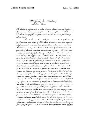
The schedule referred to in these Letters Patent and much part of the same containing a description in the words of the said William E. Fulkens himself of his improvement in the machine for building clover seed.
Be it known that I, William E. Fulkens of the County of Harrison and State of Ohio have invented a new and useful improvement in a machine for building clover seed and that the following is a full and exact description of the construction and operation of the said machine as improved by me. The clover seed miller consists of six parts. 1st frame. 2nd cylinder. 3rd conveyor. 4th caps. 5th hopper and 6th wind mill. 1st The frame is constructed of 4 posts about 3 feet 3 inches high; 2 caps about 4 feet long, 2 quills about 3 feet long, eyelet of tenons, two pianos about 2 inches in thickness and 3 feet 2 inches in length and about 1 foot in width which are placed between the caps and the quills to which the conveyor is fastened and which is raised and lowered at pleasure by means of screw bolts; and 4 ties 2 feet 3 inches long eyelet of tenons, making a frame the extreme dimensions of which are 3 feet 7 inches long; 3 feet 3 inches wide and 3 feet high allowing the timbers to be 3 inches by 3 inches. 2nd The following size and construction of a cylinder is presumed to be the best adapted to the application of a four horse power and consequently must be varied according to the power applied. Three wooden heads or two cast rings and one wooden head are snugly set upon one bar of iron of suitable size say 1½ inch square on which are formed, of wood, and bolted and screwed in iron, as many slates about an inch and a half thick and 2 feet 8 inches long, as will make a cylinder about 9¾ in diameter. On each end of the caps is turned a journal, which rests in metal bearings in bevels in the middle of the caps of the frame and held down also by metal caps. The cyl
Page 3.
United States Patent
Patent No.: X8108
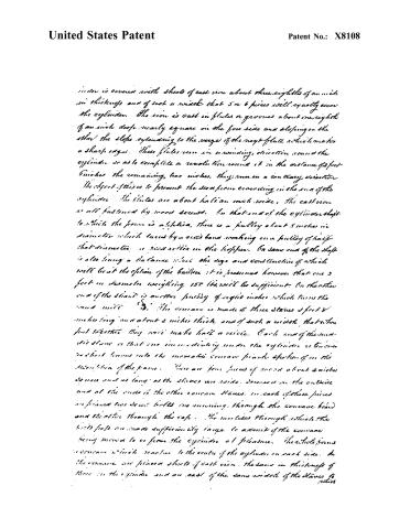
inder is covered with sheets of cast iron about three-eighths of an inch in thickness and of such a width that 5 or 6 pieces will exactly cover the cylinder. The iron is cast in flutes or grooves about one-eighth of an inch deep, nearly square on the fore side and sloping on the other; the slope extending to the verge of the next flute which makes a sharp edge. These flutes run in a winding, direction round the cylinder, so as to complete a revolution round it in the distance of feet inches; the remaining two inches, they run in a contrary direction. The object of this is to prevent the seed from crowding in the sun of the cylinder. The flutes are about half an inch wide, the cast iron is all fastened by wood screws. On that end of the cylinder shaft to which the power is applied, there is a pulley about 5 inches in diameter which turns by a belt band working on a pulley of half that diameter, in reaction in the hopper. On same end of the shaft is also hung a balance wheel the size and construction of which will be at the option of the builder; it is presumed however that one 3 feet in diameter weighing 150 lbs. will be sufficient. On the other end of the shaft is another pulley of eight inches which turns the wind mill.
3. The concave is made of three slabs 2 feet 8 inches long and about 2 inches thick and of such a width that when put together they will make half a circle. Each end of the middle slab is that one immediately under the cylinder is turned to short turns into the movable concave frame spokes of in the direction of the frame. There are four pieces of wood about 2 inches square and as long as the slabs are wide, screwed in the outside and at the ends is the other concave slabs. In each of these pieces are placed two screw bolts one running through the concave board and the other through the cap. The mortises through which the bolts pass are made sufficiently large to admit of the concave being moved to or from the cylinder at pleasure. The whole forms a concave which reaches to the centre of the cylinder on each side. In the concave are placed sheets of cast iron, the same in thickness of those in the cylinder and as cast of the same width of the slabs to which
Page 4.
United States Patent
Patent No.: X8108
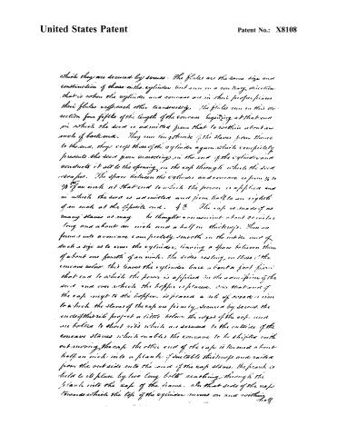
which they are secured by screws. The flutes are the same size and construction of those in the cylinder but run in a contrary direction, that is when the cylinder and concave are in their proper places their flutes cross each other transversely. The flutes run in this direction four fifths of the length of the concave beginning at that end in which the seed is admitted from that to within about an inch of back end. They run lengthwise of the slaves from there to the end. They cross those of the cylinder again which completely prevents the seed from escaping in the end of the cylinder and conducts it all to the opening in the cap through which the seed escapes. The space between the cylinder and concave is from 3/8 to 5/8 of an inch at that end to which the power is applied and in which the seed is admitted and from half to an eighth of an inch at the opposite end. 4th. The cap is made of as many slates as may be thought convenient about 30 inches long and about an inch and a half in thickness. These are formed into a concave completely smooth on the inside and of such a size as to cover the cylinder, leaving a space between them of about one fourth of an inch, the sides resting on those of the concave below. This leaves the cylinder bare about a foot from that end to which the power is applied to the admission of the seed and over which the hopper is placed. Over that end of the cap next to the hopper is placed a rib of wood or iron to which the slates of the cap are firmly secured by screws. The ends of this rib project a little below the edges of the cap and are bolted to short ribs which are screwed to the outside of the concave slates which enables the concave to be shifted with out moving the cap. The other end of the cap is tenoned about half an inch into a plank of suitable thickness and nailed from the outside into the end of the cap slates. The plank is held to its place by two long bolts reaching through the plank into the cap of the frame. On that side of the cap towards which the top of the cylinder moves on and without
104
Page 5.
United States Patent
Patent No.: X8108
half an inch of the end of the cylinder there is a mortise extending 3 inches lengthwise of the cap, and about 3½ inches crosswise. Through this opening the dead scrap is when rubbed. 5th The hopper is a square box of inch plank half an inch wider than the diameter of the cylinder and extending in length from the end of the cap to the end of the cylinder and about 7½ in height. In the top of this there is placed another box about 6½ inches high, in the shape and form of common hoppers. These two are united by screws and placed over the vacant end of the cylinder, its side resting on the concave stands. The front roller, which is about 3 and ½ inches in diameter and fitted on its surface and placed in the hopper extending over the inner side leaving a space between it and the cylinder of about half an inch on the outside of the hopper on the shape of the roller is a small pulley, secured as above described. 6th The bands are turned by the pinions on the back end of the cylinder shaft, and will require about double the number of revolutions of the cylinder. The wire mill has a separate frame, and is set under the concave and receives the scrap immediately into the circle as it falls from the rollers.
The machine is constructed and the parts and screws are shown in the ordinary manner. (Speculation.) The scrap after being thrashed off the stone and well raised is thrown into the hopper. The cylinder is put into motion at the rate of 20 revolutions per minute. The scrap takes place as the plates carried the scrap under the cap and after passing several times between, reaches the opening in the cap from which it escapes and falls into the circle of the wire mill, the wire-mill friction is driven if the scrap runs through the wire and scrap are conveyed into a box below prepared for its reception.
What I claim as my invention and improvement is the peculiar combination and arrangement of the several parts of the before described machine for cleaning a lever scrap, but I particularly claim the method of preventing the scrap from crowding in the end of the cylinder and of conducting it to the place of escape as before described.
Wm. E. Harkins
1777-18
Published accounts: journal notice
Notice in the monthly list of patents, with remarks
Journal of the Franklin Institute, new ser., vol. 14 (1834), p. 253 · View the page
71. For a Machine for Hulling Clover Seed; William E. Lukens, Cadiz, Harrison county, Ohio, March 26.
Remarks. A cylinder is to be made, the periphery of which is covered with iron, cast in segments, with indentations, or furrows, for rubbing out the seed; and under this there is to be a concave, enclosing the cylinder for nearly one-half its circumference. There is nothing special in the construction of any part, or that is likely to render it superior in any respect to the machines already in use, some of which are very similar to it. The claim is to "the peculiar combination and arrangement of the several parts, but particularly the mode of preventing the seed from crowding in the end of the cylinder, and of conducting it to the place of escape." The method of preventing the crowding, above alluded to, is the spiral direction given to the flutes on the cast iron segments of the roller, and of corresponding segments placed within the concave. There are some special directions given respecting the manner of forming and of uniting certain parts, but these, not being illustrated in the drawing, are somewhat obscure.
About this record
- Patentee
- DATAMP
- Date
- the Name and Date index of patents, DATAMP, USPTO records
- Invention
- DATAMP
- Listed in
- the Name and Date index of patents, DATAMP, USPTO records, Jim Shaw's X-patent list, the Journal of the Franklin Institute, Burke's List of Patents (1847)
- Burke's 1847 Patent Office list gives the same patent.