

Drawings and documents
National Archives restored drawings: drawing
Charles F. Voorhies' Patent Drawing for a Printing Press

National Archives, Restored Patent Drawings (Record Group 241) · Full-size scan at the National Archives · Catalog record
Show the text on the drawing Hide (54 words)
Words on the drawing as machine-read by the National Archives; not checked. Useful mainly for searching.
$3.50 / 101. Ft F1. / Mr. PRI / 101. Bed up reating / Bed / maria / bird & Platon / taking Attachment, / 8139 - X / CHARLES. F. VOORHIES / 8139 X / PRINTING PRESS. / PATENTED: BAPRIL: 1834 / have / severing Know to off the printed / Lid / Pr / ") / Perspective View. / Sectional Views.
USPTO scan
The patent as scanned by the USPTO
-
 Page 1
-
 Page 2
-
 Page 3
-
 Page 4
-
 Page 5


U.S. Patent and Trademark Office · Google Patents
Show the transcription Hide (1,477 words)
Machine transcription (LightOnOCR) of the pages as scanned by the USPTO, most of them the handwritten copies made when the records were restored after the 1836 fire. Not checked; it can misread handwriting, so compare it with the scan.
Page 1.
C.F. Voorhies.
Printing Press.
Patented Apr. 8, 1834.
No. 8139X

Page 2.
4/8/1834 8139X
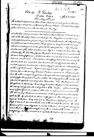
Charles F. Voorhees
Spettens Patent
Printing Press
April 8, 1834.
The schedule referred to in these Letters Patent and making part of the same containing a description in the words of the said Charles F. Voorhees himself of his improvement in the machine for Printing.
To all whom it may concern, Be it known that I Charles F. Voorhees of Essex in the County of Essex and State of New Jersey have invented a new and useful machine for printing and I do hereby declare that the following is a full and exact description thereof reference being had to the drawings which accompany and make a part of this specification. Fig 1 is a perspective view of the whole machine and Fig 2. a vertical section taken longitudinally. In both these figures the parts which correspond are marked with the same letters reference. As this machine is intended to be made both for large and small work I do not deem it necessary to give the dimensions of the respective parts as a competent machinist will readily proportion these to suit the required purpose from the printing of single cards, to that of the large volumes of book work. The frame AA may be made in different forms, that dependent on the drawing however I esteem convenient. The semicircular piece B with a corresponding piece on the opposite side supports the shaft C which passes through and revolves within the ink ing cylinder D and has a fly wheel on its opposite end to regulate the motion. When the press is at work this cylinder is stationary, it is not being to sustain the form and to distribute the ink regularly upon the ink ing rollers E E. The form is placed vertically and is figure by screws wedges or otherwise in a frame seen in section at D. The two ends of this frame are attached to sliding pieces at each end of the cylinder D. One of which is shown at Fig figure 2. These sliding pieces serve as guides to the frame, being retained in their places by proper grooves. The shaft C has on it two wheels H H close to the heads of the cylinder D which by means of two connecting rods I, joined to the piece J, carry the sliding piece and the frame to forward and backward. K is a section of the platen which is stationary, but may be set so as to regulate the pressure by means of the screw
Page 3.
26
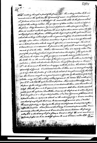
The working through a part of the frame. The working rollers E, E, are carried round the cylinder D by means of arms, one of which is shown at A, fastened at one end to the shaft C, and at the other to the frame which supports the working rollers. The guides of these rollers, cast in slots in the frame, being brought down by means of spiral or other springs, so as to keep them in contact with the cylinder D, and to force them down upon the type as they pass over the frame. Although the large surface of the cylinder D, over which the working rollers pass, will in general suffice to distribute the ink equally upon them, I incline sometimes to give to one or more of these rollers a lateral motion which may be effected in various ways. The ink is to be contained in a reservoir A formed in the cylinder D, and reaching from one end of it to the other. Within this reservoir there is a supply roller P, one part of the periphery of which projects out above the surface of the cylinder D. The pinion D, is upon one of the guides and at the working rollers receive the teeth T, on the under edge of their frame, give to the roller a punctual revolution, a latch which checks the pinion being lifted by a pin on the arm H. At the moment the teeth are to engage with the pinions, this latch is shown separately at figure 4. Contingences similar to those now in use may be employed to regulate the portion of ink which shall be brought round by this roller; this however may be in a great measure effected by the distance of its revolution, every time the working rollers pass over it. The latches S, S, catch upon pins I', I' and lift the cylinder D, in its place. These cause alternately when the frame of the working rollers comes in contact with them, and thus allow it to pass. When the frame is to be opened in a or removed, both these latches are to be raised, and the cylinder D with them, turn on its shaft so as to allow the frame to be brought into a horizontal position. I incline, by means of this machine to print action on separate sheets in the ordinary way, or to use a continuous sheet of any length that can be conveniently wound upon a roller. The mode of feeding or laying on the sheet, must of course be adapted to their different purposes. A continuous sheet may be wound upon a roller V, immediately above the frame and be conducted down between the feeding rollers U, U, or sheet may be first formed a broad or sheet. As it is common in cylinder passes on to an anvil upon X, and between rollers Y, Y. The
Page 4.
shuts are kept in their places against the ends of a form by cords or strings in a manner well known in other presses. Fig. 3. shows the manner in which the motion is communicated from the shaft C. to the feeding rollers and to the endless upon Z. is a segment wheel on the shaft, the teeth on which take into the wheel a, having on it a groove which to receive a band, this band may be wound a while, with graduated grooves on the roller b, which is the same as D. in figs 1 & 2. The roller C. round which it is also shown as passing carries the endless upon X. a is a pulley for tightening the band, whilst the blank part of the segment wheel Z. is passing round the feeding rollers, endless upon, and holding ends remain at rest, and the impression is then given by the advancing of the form against the platen, this receiving when the cranks on the shaft C. are towards the form. The ink will be passed over the form, when the cranks are in the reverse position, the faces of the type then must nearly coinciding with the surface of the cylinder D. When I print upon a continuous sheet. I intend to divide the same as it is delivered from the form by means of a knife or of perforating points which may be arranged in various ways to operate at the right time. This however being a thing of arrangement only and not affecting the general principles upon which the machine operates I do not deem it necessary to designate any particular mode of effecting this object. It will readily be perceived that although I have represented this press as operating upon one form only a second may be added on the opposite side, and furnished with all the apparatus required for its action, as in that described. This second form will receive its ink from the same roller as the first and the two may be worked by a power considerably less than that which would be required for the single form. What I claim as my invention and for which I ask a patent is the general construction of the before described machine. Many of the separate parts of which it consists are similar to those heretofore employed in printing and other machines, and these therefore I do not claim as my invention. But I do claim the ink ing cylinder with the ink ing rollers revolving round it in the manner, and the form as here described. I also claim the manner of fixing and operating upon the form by the cranks upon the shaft which passes through the centre
Page 5.
8139X
27. -
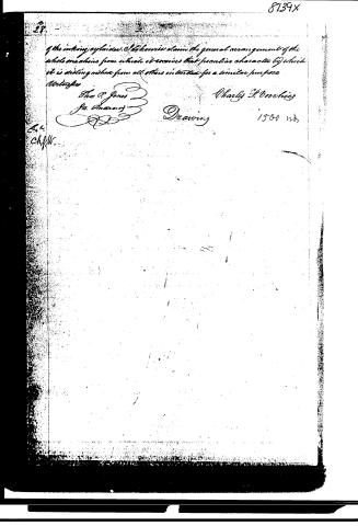
of the inking cylinders. I likewise claim the general arrangement of the whole machine from which it receives that peculiar character by which it is distinguished from all others intended for a similar purpose.
Witnesses
Thos. P. Jones
Jas. Anderson
Charles H. Voorhees
Drawing 1500 no.
E. L.
Chf. W.
Published accounts: journal notice
Notice in the monthly list of patents, with remarks
Journal of the Franklin Institute, new ser., vol. 14 (1834), p. 325 · View the page
9. For a Printing Press; Charles F. Voorhies, Newark, New Jersey, April 8.
Remarks. This printing press is one which manifests much ingenuity in the contrivance of it, but it requires the aid of drawings to make its construction known, and at a period so prolific in improvements upon this important instrument, it appears that what is new to-day, may be superceded by the contrivance of to-morrow. In the art of printing, the revolution has been as entire as in the business of locomotion, and books are produced as men travel upon rail-roads, by steam engines. We would insert the claim made by Mr. Voorhies, if, as is frequently the case, any tolerable idea of the machine could be collected therefrom, but as it refers to the previous description and the accompanying drawings, it would be unavailing.
About this record
- Patentee
- DATAMP
- Date
- the Name and Date index of patents, DATAMP, USPTO records
- Invention
- DATAMP
- Listed in
- the Name and Date index of patents, DATAMP, USPTO records, Jim Shaw's X-patent list, the Journal of the Franklin Institute, Burke's List of Patents (1847)
- Burke's 1847 Patent Office list gives the same patent.