

Drawings and documents
National Archives restored drawings: drawing
James Atwater's Patent Drawing for an Improved Furnace Stove

National Archives, Restored Patent Drawings (Record Group 241) · Full-size scan at the National Archives · Catalog record
Show the text on the drawing Hide (56 words)
Words on the drawing as machine-read by the National Archives; not checked. Useful mainly for searching.
126. STOVES & J NACES / [154] Heating St.v6a. / JAMES ATWATER'S / 126. STOVES & FURNACES Improved Furnace Stove / [154] Heating Stoves. / Parented 19April 1834 / $3 / CL CUICATION / 81.55-+ DIVISION. / 20 / 83/8 / BackVrew / Front Vies / Side view / Fij3 / Fig/ / Fig2 / of / FROM / 883 / xwa / Fig Vale / Fig IV
USPTO scan
The patent as scanned by the USPTO
-
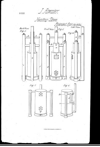 Page 1
-
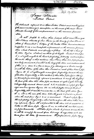 Page 2
-
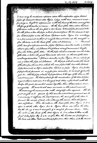 Page 3
-
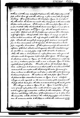 Page 4
-
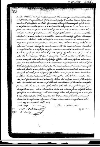 Page 5


U.S. Patent and Trademark Office · Google Patents
Show the transcription Hide (1,721 words)
Machine transcription (LightOnOCR) of the pages as scanned by the USPTO, most of them the handwritten copies made when the records were restored after the 1836 fire. Not checked; it can misread handwriting, so compare it with the scan.
Page 1.
8155X
J. Atwater.
Heating Stove.
Patented Apr. 19, 1834.
Back View
Fig. 3.
Front View
Fig. 1.
Side View
Fig. 2.
Fig. 5.
Fig. 4.
Page 2.
4/19/1834 8155X
Av. 14
Apr. 19, 1834 41
James Atwater
Letters Patent
The Schedule referred to in these Letters Patent and making part of the same containing a description in the words of the said James Atwater himself of his improvement in the common furnace stove.
To all people to whom these presents shall come, Know ye that I James Atwater of New Haven in the County of New Haven & State of Connecticut a Citizen of the United States have invented and applied to use a new & usefull improvement in the common furnace stove which I describe and specify as follows. In the top or head of the stove Fig 1. a. at about one third of its height I insert two pipes b. c. at right angles to the head & projecting laterally outward from the centre thereof a short distance then I turn these two pipes perpendicularly downward parallel to the body of the stove and continue each of them d. e. down to a base or drum f. g. standing on a level or nearly so with the bottom of the stove then I insert in each of these bases a pipe Figure II. h. at right angles or nearly so projecting toward the rear of the stove horizontally a short distance & then these pipes figure III. i. j. are turned perpendicularly upward & continued to nearly the height of the head of the stove then these pipes are turned at right angles laterally & horizontally inward toward each k. l. & inserted in a pipe of a large size round or square Figure III. in which pipes toward the front horizontally till it reaches & is inserted in the head of the stove Figure 22 m. also in the rear of the stove below the grate & at as low a point above the dust pan Fig. 1. n. as is convenient. I insert a pipe Figure III. o projecting horizontally a short distance from the stove & then turning upward Figure III. p. & parallel to the stove till it meets & is inserted in the same pipe Figure II. m. on which the two last mentioned or pipes terminate. All these pipes should be placed so near the stove as not to occupy too much space but may be regulated as to distance from the stove by convenience. The perpendicular pipes Figure
Drawing
Page 3.
416.
1. d, e, s may be continued upwards above their respective upper lateral pipes if desired & terminated (Figure I p, q, with some ornament comes - depending on height & appearance with the head of the stove as may please the fancy of the maker or owner. On the head of the stove above the part of the same whence the two first or two lower lateral pipes proceed & below the place where the pipe which proceeds from the two second or upper lateral pipes enters the head, I place a valve (Figure I, v, revolving on a pin or similar so that it may be turned & close up the draught or open the same into the head of the stove at pleasure; ... On each of the two front perpendicular pipes I place a similar valve s, t, which closes or opens them at pleasure & is placed at any convenient height from the bottom of the stove. On the pipe which is inserted near the bottom of the stove or below the grate & proceeds upwards in the rear of the stove as already described, I place a similar valve (Figure III, w, which opens or closes this pipe at pleasure. On the pipe which enters the head of the stove from the rear & in which the rear pipe & the two other lateral pipes terminate as before described I place a pipe (Figure I, r, (or two pipes) which proceeds in any proper direction to conduct off smoke gas &c. All the pipes should be proportioned to the size of the stove in the usual manner. The best material for the construction of the stove & pipes is good sheet or cast iron & a lining of soap stone or fire brick with the back for the grate somewhat nearer together than those used in common grates. The doors & ash draw are made in the usual manner. The doors may be ornamented with iron cast when required. The object sought to be gained by this combination & arrangement are to economize & diffuse the heat & govern the draught of the stove & prevent the escape of dust when cleaning the same. These things are done as follows. When the valve in the head of the stove (Figure I, v) is open & all the others (Figure I, s, t; Figure III, w, are shut the stove has the strong & direct draught of a common furnace stove. When the valve in the head of the stove (Figure I, v) is closed & those in the front side pipes (Fig I, s, t), are open then the heated air passes from the head into these last-mentioned pipes & from thence into the doors
Page 4.
thence into the near side pipes & upwards thro' them & finally into the pipe which leads off into the chimney or flue or some other part of the building. If one of the valves in the side pipes Figure I. e. t. is open & the other shut, the heated air will then be confined to the side on which the open valve is found. If the valve in the near pipe Figure III. w. is open & all the others shut & also the lower doors Figure I. w. y. & pan k. leaving only the upper door Figure I. y. then the draught is downwards thro' the fuel into the back pipe and upwards thro' that pipe only & off as before. And if all the doors Figure I. w. y. & pan k. are open & valves as last mentioned the only draught is still thro' the back pipe. Should the draught for carrying off the dust and causing the fire to burn downwards not be required, the last described or back pipe may then be omitted. If the improvement for the retention & diffusion of the heat should not be required then the side pipes may be omitted or one side pipe only with its valve be retained.
When the stove is to be placed in a fire place some change in its structure will be required to fit it for that object. The head may be shortened as seen in Figure IV. & the valve placed in a pipe Figure IV. a, & closed or opened with a rod or handle Figure IV. b, coming to the front of the stove. The valve also in the back pipe Figure IV. c. will need to be opened and shut with a similar rod & both rods must be connected with the front of the valve by means of a lever or lever so that the rods will open or shut the valve by moving backward & forward. The valves in the side pipes Figure V must be placed as before described & as seen in Figure I. e. t. A slight change is also requisite in the communication of the side pipes with the pipe which leads from the stove and conducts away the smoke, gas &c.
This change as seen in Figure IV. a. Figure V. exhibits a front view of such a fire place stove with its doors a, f, g. & pan k. This will be sufficiently understood without further description. The only object in exhibiting this form of the improvement is to show how the invention while it retains the whole principle on which it is based can be accommodated to the place on which the instrument is to be used.
Page 5.
4/19/1834 8/55x
418.
used. I claim as my improvement the arrangement, combination, adaptation & adjustment of the several pipes & valves herein before described & specified so that by means thereof the draught of the stove is at pleasure either upward & direct thro' the fuel as in the common furnace stove or upward thro' the fuel & in direct & circuitous thro' a pipe or series of pipes near the body of the stove or downward thro' the fuel & a rear pipe & in either case ultimately off in the usual manner. I claim also the right to make use & run stoves with any two of said draughts in combination that is to say with said upward & direct draught combined with the said upward & indirect draught thro' a side pipe or pipes as above described & without the downward draught of said thro' the fuel & passing off thro' a rear pipe. And also the said upward & direct draught in combination with the downward draught thro' the fuel & passing off thro' the rear pipe as above described & without the upward & indirect draught of said thro' the fuel & the side pipe or pipes. And also the said upward & indirect draught thro' the fuel & a side pipe or pipes in combination with the downward draught thro' the fuel & passing off thro' a rear pipe as above described without the said upward & direct draught. And I claim no particular part of the instrument separately taken but only so much of the apparatus in combination as accomplishes the combination of the various draughts (2, or) neither the combination of the whole of the three draughts nor of any two of the same. And I make a separate claim for each of the above specified combinations. In testimony that the foregoing is a true, full, & exact description of the construction & operation of said machine as invented & improved by me, I have hereunto set my hand this 23rd day of March A.D. 1834.
Witness
James H. H.
172: 0.0.
Published accounts: journal notice
Notice in the monthly list of patents, with remarks
Journal of the Franklin Institute, new ser., vol. 14 (1834), p. 332 · View the page
29. For an improvement in the common Furnace Stove; James Atwater, New Haven, Connecticut, April 19.
Remarks. The stove designed is of the ordinary vertical, cylindrical form. From the head, or cap, of this stove, two draft pipes are to project horizontally from opposite sides; these are then to bend down and extend as low as the floor, parallel to the body of the stove, on each side of it; they are then to bend back horizontally, and afterwards to ascend vertically, and both to unite in one common pipe of larger dimensions, which is to lead into a chimney, or other proper place of exit. There are to be valves in the respective pipes to regulate and direct the draft, as may be desired; and some directions are given respecting the grate bars, and other appendages, which do not affect the general principle. The claims made are to the adjustment of the several pipes and valves, so that the draft may be made to pass directly upwards through the fuel, or have an indirect course through a series of pipes near the body of the stove; or downward through the fuel, and a rear pipe, and ultimately pass off in the usual manner. The combination of any two of said drafts is also claimed, but the particular parts, individually, are not claimed as making any part of the invention. We could find some stoves, patented and unpatented, with pipes and valves so arranged as to bear much resemblance to the foregoing, and we greatly err if the same principle does not obtain in some of the patented contrivances of Mr. Atwater himself.
About this record
- Patentee
- DATAMP
- Date
- the Name and Date index of patents, DATAMP, USPTO records
- Invention
- DATAMP
- Listed in
- the Name and Date index of patents, DATAMP, USPTO records, Jim Shaw's X-patent list, the Journal of the Franklin Institute, Burke's List of Patents (1847)
- Burke's 1847 Patent Office list gives the same patent.