

Drawings and documents
National Archives restored drawings: drawing
W. B. Dobson's Patent Drawing for An Assistant Striker

National Archives, Restored Patent Drawings (Record Group 241) · Full-size scan at the National Archives · Catalog record
Show the text on the drawing Hide (120 words)
Words on the drawing as machine-read by the National Archives; not checked. Useful mainly for searching.
MET FORGING / Olivers, / NAME / "netals "Dammers / $200 / CLASSIFICATION / 8167* / DIVISION / WB DOBSON / A. sills / B. upright supporters / ASSISTANT STRIKER / C Crops Beam / D. Hammer arle / E. Hammer Helve / Patented 25th april 1834. / F' Iron Band / G Wire spring / H Wedge / T.J.K. #2,3 $ 4th hiadles / M. upright supports for Treadles / N. Reacting spring / D. Chains with Hooks to adjust therese and dally the Hammer / P. Peice checking the Hammer / Q. Lever to move the striker / Helve, as secured 70.Axle / Geor Strickland D'g" / Patent office 15th Sept 1838, / Made under the direction of the of Patent / in conformity with act 3 Harch 1837 / box miproner of Patents
USPTO scan
The patent as scanned by the USPTO
-
 Page 1
-
 Page 2
-
 Page 3
-
 Page 4
-
 Page 5
-
 Page 6
-
 Page 7


U.S. Patent and Trademark Office · Google Patents
Show the transcription Hide (2,897 words)
Machine transcription (LightOnOCR) of the pages as scanned by the USPTO, most of them the handwritten copies made when the records were restored after the 1836 fire. Not checked; it can misread handwriting, so compare it with the scan.
Page 1.
8167X
W.B. Dobson.
Oliver.
Patented Apr. 25, 1834.
THE GRAPHIC CO. PHOTO-LITH. 39 & 41 PARK PLACE, N.Y.
Page 2.
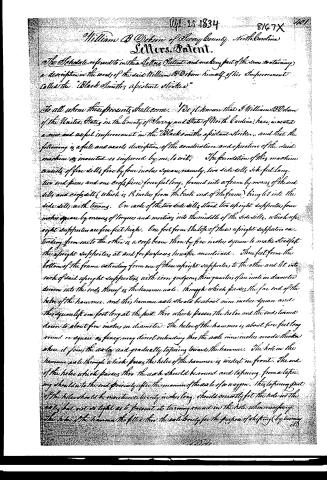
William B. Dobson of Horry County, North Carolina
Letters Patent.
The Schedule referred to in the Letters Patent and making part of the same containing a description in the words of the said William B. Dobson himself of his Improvement called the "Blacksmith's aistant striker"
To all whom these presents shall come. Ye it is known that I William B. Dobson of the United States in the County of Horry and State of North Carolina have invented a new and useful improvement in the "Blacksmith's aistant striker" and that the following is a full and exact description of the construction and operation of the said machine as invented or improved by me to wit: The foundation of this machine consists of five sills five by four inches square, namely, two side sills six feet long, two end pieces, and one cross piece four feet long, formed into a frame by means of the end sills and cross sills (which is 18 inches from the back end of the frame) being let into the side sills with tenons. On each of the two side sills stand two upright supports four inches square by means of tenons and mortises into the middle of the side sills, which upright supports are five feet high. One foot from the top of these upright supports extending from one to the other is a cross beam three by five inches square to make steady the upright supports at and for purposes hereafter mentioned. Three feet from the bottom of the frame extending from one of these upright supports to the other and let into each of said upright supports with iron gudgeons three quarters of an inch in diameter driven into the ends thereof is the hammer axle through which passes the far end of the helve of the hammer, and this hammer axle should be about nine inches square and three quarters of a foot long at the foot, this which passes the helve and the ends turned down to about five inches in diameter. The helve of the hammer is about five feet long round or square as fitters may direct extending thro' the axle nine inches made thicker when it joins the axle and gradually tapering towards the hammer. The hole in the hammer axle through which passes the helve of the hammer is widest in front. The end of the helve which passes thro' the axle should be round and tapering from a tapering shoulder to the end, and finally after the manner of the axle of a wagon. This tapering part of the helve should be maintained twenty inches long, should exactly fit the hole in the axle but not so tight as to prevent its turning round in the hole when necessary. The helve of the hammer the fitter thro' the axle only for the purpose of shifting (by turning it)
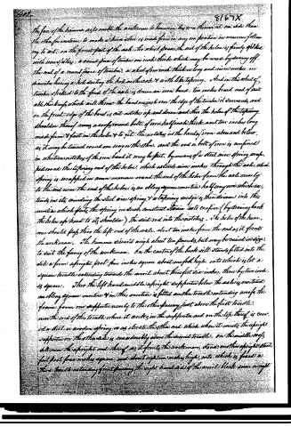
Page 3.
the face of the hammer so as to enable the workman to hammer his iron thinner at one side than the other, for instance, to make a thin edge is made firm in any one position in manner following to wit: on the front part of the axle, for which passes the end of the hole is firmly spiked with iron spikes, a round piece of timber one inch thick which may be made by sawing off the end of a round piece of timber, a wheel of one inch thick or long and nine inches in diameter having a hole during the hole in the axle & with like tapering. And in this wheel of timber spiked to the front of the axle is drawn an iron band: two inches broad and of quite able thickness which will throw the band one inch over the edge of the timber it surrounds, and on the front edge of the band is cut notches up and down and then the hole of the tapering shoulder thereof runs a cross round bolt of iron half inch thick and ten inches long made firm & fast in the hole & to get the notches in the band of iron above and below as it may be turned round one way or the other, and the rod or bolt of iron is confined in what remains of the iron band it may be fast, by means of a steel wire spring wrapped round the tapering end of the hole, which extends nine inches through the axle, this spring is wrapped in some manner round the end of the hole from the axle nearly to the end near the end of the hole is an oblong square mortice half way over which extends in its winding the steel wire spring & a tapering wedge is then driven into this mortice which fasts the spring in such constant strain as to confine (by drawing back the hole up hard to its shoulder) the said rod into the notches. The hole of the hammer should pass thro' the left end of the axle, about ten inches from the end as it fronts the workman. The hammer itself will weigh about ten pounds, but may be varied in size to suit the fancy of the workman. On the centre of the back sill stands fitted into the sill a firm upright post five inches square about one foot high, into which is let a square treadle extending towards the anvil about three feet six inches, three by two inches square. Thro' the left hand middle upright supported below the axle is mortised an oblong square mortice & in this mortice is fitted another treadle extending across the frame from one support nearly to the other passing just above the first treadle near the end of this treadle where it works in the support and on the top thereof is crested a steel or wooden spring so as to elevate the other end which when it meets the upright supported on the other side is considerably above the second treadle. On the middle cross bar near the upright end thereof as it fronts the workman, stands another upright steel foot post five inches square, and about eighteen inches high, into which is fixed a third treadle extending from passing the right hand side of the anvil block iron weight
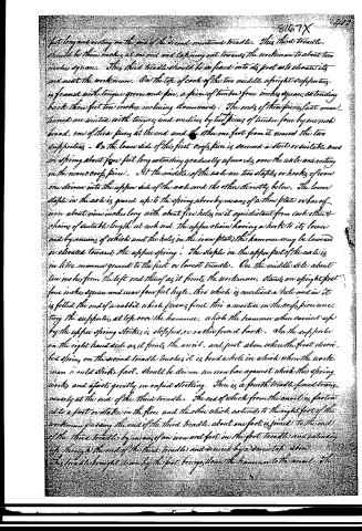
Page 4.
fit long and resting on the end of the second mentioned treadle. This third treadle should be three inches at one end and tapering out towards the workman to about two inches square. This third treadle should be so fixed into its post as to elevate its end near the workman. On the top of each of the two middle upright supports is framed with tongue grooves and pins, a piece of timber four inches square, extending back three feet ten inches, inclining downwards. The ends of these pieces last mentioned are united with tongues and mortices by two pieces of timber four by one inch broad, one of them pieces at the end and the other one foot from it secured the two supports. On the lower side of this first cross piece is secured a steel or suitable iron spring about four feet long extending gradually upwards over the axle and resting on the near cross piece. At the middle of the axle are two staples or hooks of iron, one driven into the upper side of the axle and the other directly below. The lower staple in the axle is geared up to the spring above by means of a thin plate or bar of iron about nine inches long with about five holes in it equidistant from each other & chains of suitable length at each end. The upper chain having a hook to its lower end by means of which and the holes in the iron plate, the hammer may be lowered or elevated towards the upper spring. The staple in the upper part of the axle is in like manner geared to the first or lowest treadle. On the middle side about ten inches from the left end thereof as it fronts the workman, stands an upright post four inches square and near four feet high, this which is mortised a hole and in it is fitted the end of a rabbit which passes front this a mortice in the cross piece supporting the supports, at left over the hammer, which the hammer when carried up by the upper spring strikes, is stopped, or rather forced back. On the upper side on the right hand side as it fronts the anvil, and just above where the first described spring on the second treadle touches it, is bored a hole in which when the workman would strike fast, should be driven an iron bar against which this spring works and affects greatly in rapid striking. There is a fourth treadle fixed transversely at the end of the third treadle. The end of which from the anvil is fastened to a post or stake in the floor and the other which extends to the right foot of the workman passing the end of the third treadle about one foot, is joined to the end of the third treadle by means of an iron rod fast in the first treadle and extending up through the end of the third treadle and secured by a screw tap above. This treadle brought down by the foot brings down the hammer to the anvil.
Page 5.
The face of the hammer is to enable the workman to hammer his iron thinner at one side than the other, for instance, to make a shoe shoe is made from in any one direction in manner following to wit: on the front part of the axle, for which passes the end of the helve is firmly spiked with iron spikes, a round piece of timber one inch thick which may be made by sawing off the end of a round piece of timber, a wheel of one inch thick or long and nine inches in diameter having a hole cutting the hole in the axle & with like tapering. And in this wheel of timber is spiked to the front of the axle is drawn an iron band, two inches broad and of suitable thickness, which will throw the band one inch over the edge of the timber it surrounds, and on the front edge of the band is cut notches up and down and then the helve of the tapering shoulder thereof runs a crooked round bolt of iron half inch thick and ten inches long made firm & fast in the helve & to fit the notches in the band of iron above and below, as it may be turned round one way or the other, and the rod or bolt of iron is confined in whatver notches of the iron band it may be fast, by means of a steel wire spring wrapped round the tapering end of the helve, which extends nine inches through the axle, which spring is wrapped in common manner round the end of the helve from the axle nearly to the end near the end of the helve, is an oblong square mortice half way down which extends in its winding the steel wire spring & a tapering wedge is then driven into this mortice which puts the spring in such constant strain as to confine (by drawing back the helve up hard to its shoulder) the said rod into the notches. The helve of the hammer should pass thru the left end of the axle, about ten inches from the end as it fronts the workman. The hammer should weigh about ten pounds, but may be varied in size to suit the fancy of the workman. On the centre of the back side stands fitted into the side a firm upright post, four inches square about one foot high, into which is let a square treadle extending towards the anvil about three feet six inches, three by two inches square. Thru the left hand middle upright supported below the axle is morticed an oblong square mortice & in this mortice is fitted another treadle extending across the frame from one support nearly to the other passing just above the first treadle, near the end of this treadle where it works in the supports and on the top thereof is cranked a steel or wooden spring or as elevate the other end which when it meets the upright supports on the other side is considerably above the second treadle. On the middle of the side near the upright end thereof as it fronts the workman, stands another upright steel fast post four inches square, and about eighteen inches high, into which is fixed a third treadle extending from passing the right hand side of the anvil block down straight
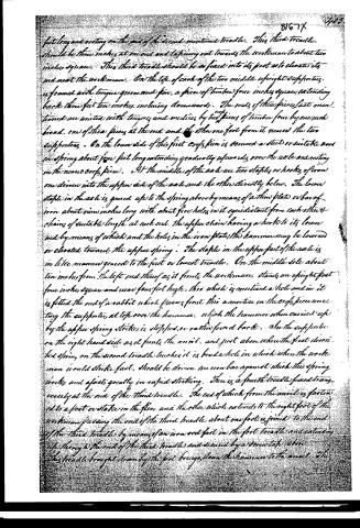
Page 6.
put long and resting on the end of the second mentioned treadle. This third treadle should be three inches at one end and tapering out towards the workman to about two inches square. This third treadle should be so fixed into its post as to elevate its end near the workman. On the top of each of the two middle upright supports is framed with tongue groove and pin, a piece of timber four inches square extending back three feet two inches inclining downwards. The ends of these pieces last mentioned are united with tongues and mortices by two pieces of timber four by one inch broad, one of these pieces at the end and the other one foot from it nears the two supports. On the lower side of this first crofs pin is screwed a steel or suitable iron spring about four feet long extending gradually upwards over the axle and resting on the near crofs piece. At the middle of the axle are two staples or hooks of iron one driven into the upper side of the axle and the other directly below. The lower staple in the axle is geared up to the spring above by means of a thin plate or bar of iron about nine inches long with about five holes in it equidistant from each other & chains of suitable length at each end. The upper chain having a hook to its lower end by means of which and the holes in the iron plate, the hammer may be lowered or elevated towards the upper spring. The staple in the upper part of the axle is in like manner geared to the first or lowest treadle. On the middle side about ten inches from the left end thereof as it fronts the workman, stands an upright post five inches square and near four feet high, this which is mortised a hole and in it is fitted the end of a rabbit which passes front this a mortice in the crofs piece connecting the supports, at top over the hammer, which the hammer when carried up by the upper spring strikes, is stopped, or rather forced back. On the support on the right hand side as it fronts the anvil, and just above where the first driven steel spring on the second treadle touches it is bored a hole in which when the workman would strike fast, should be driven an iron bar against which this spring works and aforesaid greatly in rapid striking. There is a fourth treadle fixed transversely at the end of the third treadle. The end of which from the anvil is fastened to a post or stake in the floor and the other which extends to the right foot of the workman placing the end of the third treadle about one foot is joined to the end of the third treadle by means of an iron and fast in the foot treadle and extending up through the end of the third treadle and secured by a screw tap above. This treadle brought down by the foot brings down the hammer to the anvil.
Page 7.
front end of the machine being led on a flat thin piece of timber with holes bored in the side near the end and a short piece of timber being on one side into the front side extending over these holes having also a hole in it over the lower holes. The front part of the striker may be easily moved from side to side with a small iron or wooden lever. This machine may be made of greater or less dimensions by changing the proportions above described. Of this machine, the hammer its tube the seal the simple principle of making it with a lever and the lower part of the frame are old. The balance thereof the improvement. That the above described machine and all and every part thereof is new except as above. I do testify that the above is a true specification of leave hereunto set my hand April 1st 1824.
Witnesses:
Winston Thomas
John Jefferson Ward
Wm B. Dobson
Drawing
About this record
- Patentee
- DATAMP
- Date
- the Name and Date index of patents, DATAMP, USPTO records
- Invention
- DATAMP
- Listed in
- the Name and Date index of patents, DATAMP, USPTO records, Jim Shaw's X-patent list, Burke's List of Patents (1847)
- Burke's 1847 Patent Office list gives the same patent.