

Drawings and documents
National Archives restored drawings: drawing
C. Evan's Patent Drawing for a Method of the Prevention of Steam Boiler Explosions

National Archives, Restored Patent Drawings (Record Group 241) · Full-size scan at the National Archives · Catalog record
Show the text on the drawing Hide (43 words)
Words on the drawing as machine-read by the National Archives; not checked. Useful mainly for searching.
122. STEAM-BUILERS, / Indicators. / C. EVANS' / Tors / Patented 8th May 1834. / #2 - Prevention of Steam Boiler Explosions / Volig 19 pag C521. / CLASSIFICATION / 8185-x / IIV ISION. / Fig.4. / T' / Fig 1 / Fig. / Fig3. / Is
USPTO scan
The patent as scanned by the USPTO
-
 Page 1
-
 Page 2
-
 Page 3
-
 Page 4
-
 Page 5
-
 Page 6
-
 Page 7


U.S. Patent and Trademark Office · Google Patents
Show the transcription Hide (1,863 words)
Machine transcription (LightOnOCR) of the pages as scanned by the USPTO, most of them the handwritten copies made when the records were restored after the 1836 fire. Not checked; it can misread handwriting, so compare it with the scan.
Page 1.
8185X
C. Evans,
Steam Safety Valve.
Patented May 8, 1834.
Fig. 4.
Fig. 1.
Fig. 3.
Fig. 2.
A.M. PHOTO-LITHO. CO. N.Y. (OSBORNE'S PROCESS)
Page 2.
8185X May 8, 1834 521
Cadwallader Evans of Philadelphia
Letters Patent
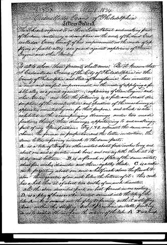
The Schedule referred to in these Letters Patent and making parts of the same containing a description in the words of the said Cadwallader Evans himself of his improvement in the mode of applying a fusible alloy as a guard against explosions of Steam Engines and other Boilers.
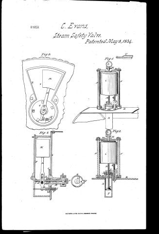
To all to whom these presents shall come: Be it known that I Cadwallader Evans of the City of Philadelphia in the County of Philadelphia and State of Pennsylvania, have invented a new and useful improvement in the mode of applying a fusible alloy as a guard against... explosions of Steam Engines and other Boilers, and that the following is a full and exact description of the construction and operation of the machinery or apparatus invented by me for that purpose, and which is also exhibited in the accompanying drawings under two modifications thereof. These drawings appertaining to and making a part of my Specification. Fig 1. & 2. represent the same machine, the former in perspective and the latter in section, the same letters referring in each to the same parts.
A. is a tube of Brass or other metal about five inches long and about one and a quarter inch bore, and one eighth thick at its sides and bottom. B is a flanch or plate of the same metal about five inches diameter and three eighths thick. C is a valve cock projecting about one and a half inch above the flanch & about three quarters of an inch below the bottom of it: this cock has a hole thro' it of about two tenths of an inch diameter.
all the above described parts are best formed in one casting. D. is a plug of brass or other metal screwed into the top of the tube A. E. is screwed into the plug D forming with it a stuffing box, within this stuffing box is placed some suitable packing so as to exclude the air from the interior of the tube A. I wish
Page 3.
22. 8185x May 8, 1834
a mass of fusible alloy that will melt at the required temperature. G is a button or piece of brass or iron, about three quarters of an inch in diameter and resting on the alloy. H is a brass or iron stem about three eighths in diameter, which is fastened to G and passes through the stuffing box, and is screwed into the bottom of I, a weight which may be equal to thirty pounds, or more. K is a round piece of metal of about half an inch in diameter screwed into the top of the weight I. L is a handle for the purpose of raising the weight when required. M is a guard placed across the top of the weight and about a quarter of an inch above it. When the weight is supported by the piece G as it rests on the alloy, the top of the guard should be about half an inch below the bottom of the handle L, so that when the alloy melts, the weight will descend until the handle will rest on the guard; this guard is also intended to keep the weight in its upright position by means of the round iron piece K, passing through a hole in the centre of said guard. N.N. are two rods about half an inch in diameter which are fastened to the flange B, and are of sufficient length to support the guard M. O is a small valve fitted to the bottom of the valve cock, to this valve is secured a small stem which passes through the cock and extends up to within about a quarter of an inch of the bottom of the weight; on the top of this stem is a button of metal P, which may be about half an inch in diameter. Q is a spiral spring for the purpose of keeping the valve up to its place. R represents the top of the boiler to which the apparatus is bolted, with the tube A containing the fusible alloy projecting into the interior of the boiler, as also does the lower end of the valve cock, as seen at O.
The operation of the above described apparatus is as follows. The fusible alloy E is so made as to melt at a temperature a little above the regular working temperature of the steam in the boiler. That is to say if in a high pressure boiler the safety
Page 4.
8185x
May 8, 1834
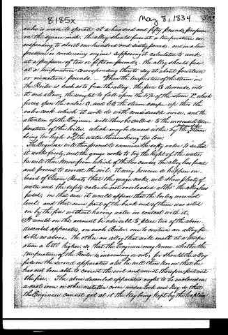
valve is made to operate at a hundred and fifty pounds pressure on the square inch. The alloy should fuse at a temperature corresponding to about one hundred and sixty pounds, and in a low pressure or condensing engine supposing it calculated to work at a pressure of ten or fifteen pounds, the alloy should fuse at a temperature corresponding thereto say at about fourteen or nineteen pounds. When the temperature of the steam in the Boiler is such as to fuse the alloy, the piece G descends into it and allows the weight to fall upon the tip of the stem P, which forces open the valve O, and lets the steam escape up thro' the valve cock which it will do with considerable noise, and the attention of the Engineer will thus be called to the increased temperature of the boiler, which may be caused either by the steam being too high or the water therein being too low.
The Engineer will then proceed to examine the safety valve to see that it works freely, and the gauge cocks to try the height of the water. He will then know from which of the two causes the alloy has fused, and proceed to correct the evil. It may however so happen on board of Steam Boats that the gauge cocks will show plenty of water and the safety valve be not overloaded although the alloy has fused; in that case it would appear that the boilers were not level, and that some part of the back end of them was acted on by the fire without having water in contact with it.
It would on this account be advisable to place two of the above described apparatus, on each Boiler, one to contain an alloy fusible as above, the other an alloy that will melt at a temperature a little higher, so that the Engineer may know whether the temperature of the Boiler is increasing or not; for should the alloy fuse in the second apparatus also he will then know that he has not been able to correct the evil and must therefore put out the fire. The above described apparatus ought to be enclosed in a cast iron or other metallic cover under lock and key so that the Engineer cannot get at it the key being kept by the boat
Page 5.
on the screw when duty it will be to raise the weight when the apparatus has gone into operation and to place the forked piece S between the guard and the handle so that the alloy may congeal in its place, and be ready for another operation. The fork is then to be removed and the box locked. Fig 3 represents a sectional view of another modification of this machine and fig 4 is a front view of it as it appears on the outside of the boiler head.
A is a hollow metallic cylinder, the interior of which is about one inch long and about two inches in diameter, and it may be about one eighth of an inch thick. B is a round part of the same piece of metal about two and half inches long connecting the cylinder to the flanch C, which is about five inches in diameter and three eighths thick. The interior of B is in the form of the frustum of a cone, the base of which joins the cylinder A, the diameter being about one inch and extending towards the flanch about one and a quarter inch where it is about three quarters of an inch in diameter. This part of the interior of B is made conical for the purpose of preventing the alloy which is placed in A from getting towards the flanch. The above described form the interior of A & B may be given to it in casting by means of a core, and that part which forms the hole thro which the shaft D passes may be drilled as also may the cavity to receive the plug E, and form the stuffing box F in a valve cock similar to that in the first described apparatus. G is a small lever the arms of which are at right angles to each other one laying atop, and a little above the lever H, the other standing upright and having the stem of the valve I, passing thro it. On this stem are screwed two small round pieces of metal about half an inch in diameter, one of them being placed between the small lever and the flanch, and the other on the opposite side of the lever. The one on the side next the flanch is to receive the pressure of the lever to open the valve, the other is to shut it, as the back of the small lever presses against it.
Page 6.
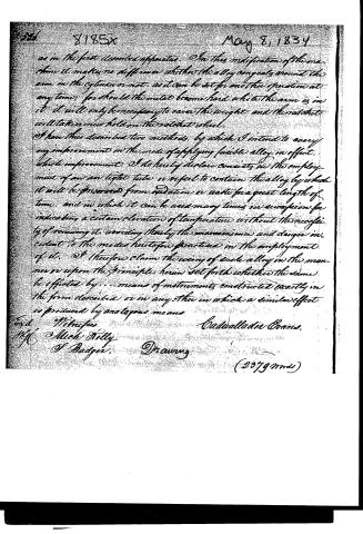
8185X …
Page 7.
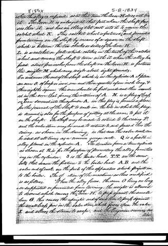
as in the first described apparatus. In this modification of the machine it makes no difference whether the alloy congeals around the arm in the cylinder or not, as it can be set for one time operation at any time; for should the nut become hard while the arm is in it it will only be necessary to raise the weight and the ratchet will take a new hold on the ratchet wheel.
I have thus described two methods, by which I intend to carry my improvement in the mode of applying fusible alloy in effect, which improvement I do hereby declare consists in the employment of an air tight tube or vessel to contain the alloy by which it will be preserved from oxidation or waste for a great length of time, and in which it can be used many times in succession for indicating a certain elevation of temperature without the necessity of renewing it, avoiding thereby the inconveniences and dangers incident to the modes heretofore practiced in the employment of it. I therefore claim the using of such alloy in the manner or upon the principle herein set forth whether the same be effected by means of instruments constructed exactly in the form described or in any other in which a similar effect is produced by analogous means.
Ford W. Trufus
Mfr. Mich. Kelly
J. Badger.
Drawing
(2379 mds)
Published accounts: journal notice
Notice in the monthly list of patents, with remarks
Journal of the Franklin Institute, new ser., vol. 14 (1834), p. 391 · View the page
7. For Preventing Explosions in Steam Boilers; Cadwallader Evans, Engineer, city of Philadelphia, May 8.
Remarks. This patent is taken for "an improvement in the mode of applying the fusible alloy as a guard against explosions of steam engine, and other boilers." Those acquainted with the various devices which have been proposed, and adopted, for the prevention of explosions, know that a fusible alloy, which shall melt by the temperature of the water, or steam, before it rises so high as to be dangerous, has been applied in various ways, and that in France its employment is legally enforced. As hitherto employed, it is liable to several objections, among which is the alteration which the alloy itself undergoes, by fusion in contact with atmospheric air; becoming thereby, to a certain extent, oxidized, and, consequently, having its fusing point changed. Another objection has arisen from the fusion of these disks giving a vent to the steam, through an aperture which could not be closed until the contents of the boiler had become cooled; a circumstance not only attended with delay, but sometimes pregnant with real danger, as the boat, deprived of the action of the engine, may be actually driven on shore. Both these sources of danger are guarded against by the invention of Mr. Evans, in a way which promises to be perfectly effectual, and some idea of which may be collected from the following claim: "I have thus described two modes in which I intend to carry my improvement in the mode of applying a fusible alloy into effect, which improvement, I do hereby declare, consists in the employment of an air tight tube, or vessel, to contain the alloy, by which it will be preserved from oxidation, or water, for a great length of time, and in which it can be used many times in succession for indicating a certain elevation of temperature, without the necessity of renewing it; avoiding thereby the inconvenience and danger incident to the modes heretofore practised in the employment of it. I therefore claim the using of such alloy in the manner, or upon the principle, herein set forth, whether the same be effected by means of an instrument constructed exactly in the form described, or in any other in which a similar effect is produced by analogous means." The alloy, when in the solid state, sustains a weighted arm, by enclosing, and holding, a piece of metal attached to the end of a journal, which passes through the box; but when the metal fuses, the weighted arm, which is on the outside of the box, descends, and, in doing so, gives notice, by opening a valve for the escape of steam.
About this record
- Patentee
- DATAMP
- Date
- the Name and Date index of patents, DATAMP, USPTO records
- Invention
- DATAMP
- Listed in
- the Name and Date index of patents, DATAMP, USPTO records, Jim Shaw's X-patent list, the Journal of the Franklin Institute, Burke's List of Patents (1847)
- Burke's 1847 Patent Office list gives the same patent.