

Drawings and documents
USPTO scan
The patent as scanned by the USPTO
-
 Page 1
-
 Page 2
-
 Page 3
-
 Page 4
-
 Page 5
-
 Page 6
-
 Page 7
-
 Page 8
-
 Page 9
-
 Page 10
-
 Page 11
-
 Page 12
-
 Page 13
-
 Page 14
-
 Page 15


U.S. Patent and Trademark Office · Google Patents
Show the transcription Hide (6,089 words)
Machine transcription (LightOnOCR) of the pages as scanned by the USPTO, most of them the handwritten copies made when the records were restored after the 1836 fire. Not checked; it can misread handwriting, so compare it with the scan.
Page 2.
United States Patent
Patent No.: X8217
Isaac Drake of Minot Maine
Letters Patent
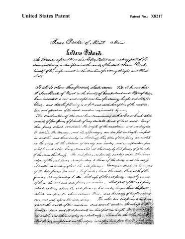
The Schedules referred to in this Patent and making part of this same containing a description in the words of the said Isaac Drake himself of his improvement in the Machine for sawing shingles and Blind slats.
To all to whom these presents shall come. Be it known that I Isaac Drake of Minot in the County of Cumberland and State of Maine have invented a new and useful machine for sawing shingles and slats for blinds, and that the following is a full and exact description of the construction and operation of the said machine as invented by me.
The construction of the machine commences with a bed or bench which consists of four pieces of planks of any suitable kind of hard wood. Two of these pieces which constitute the length of the machine and are designed to sustain the carriage and its appendages are ten feet in length, one foot in width, and three inches in thickness. The four of bed pieces are cut on the edges at the distance of twenty one inches, and in a position parallel to each other being connected at the ends by two pieces of planks of the same thickness. The end pieces are twenty inches wide. The lower edges of the end pieces corresponding to those of the sides and the edges of width extending above the side pieces. Grooves are made in the inside of the bed pieces two and a half inches from the ends, the width of the grooves corresponding to the thickness of the end pieces, and by means of these the end and side pieces are united. That part of the end pieces which extends above the side pieces is ten inches longer than the part which occupies the space between them, and the ends of length extend over and rest upon the side pieces. The other two bed pieces which constitute the width of the machine and serve to sustain the shaft of the circular saw and its dependents are five feet in length, twelve inches in width and three inches in thickness. These like the other pieces of bed pieces are placed on the edges, in a position parallel to each other.
Page 3.
United States Patent
Patent No.: X8217
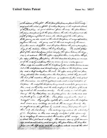
at the distance of three feet. The two pairs of bed pieces are placed transversely across each other which is effected by cutting two grooves in the underside of each of the long bed pieces, at equal distances from the ends. The space between the grooves corresponding to the space between the other bed pieces and the width of the grooves fitted to receive the thickness of the other pieces. Like grooves are also made in the short bed pieces at unequal distances from the ends. The grooves next to the end occupied by the saw being two and a half feet, and the space between the grooves corresponding to the distance between the long bed pieces. The width of that part of the short bed pieces which occupy the space between the long ones is so reduced that the upper edges fall three inches below the upper edges of the long bed pieces. The last described bed pieces are connected at the ends by end pieces that are seven by nine inches square. These ends are united with the bed pieces by two suitable tenons on each end of the end pieces and corresponding mortises in the bed pieces made two and a half inches from the ends. The upper sides of the end pieces being elevated two inches above the bed pieces which they connect. The bed of the machine thus formed is supported by four sills of suitable dimensions, one sill being placed under each end of each pair of bed pieces. The ends of the bed pieces being sunk in suitable grooves or mortises made in the sills and the sills confined to the floor of the building in which the machine works. On the inside and at the upper edges of the long bed pieces are two plates of iron two inches wide and one fourth of an inch thick. These plates may be either cast or wrought iron. They receive eighths of an inch above the bed pieces and serve as a railway on which the carriage travels. They are confined in their places by suitable screws that pass through them into the bed pieces. The railway may extend the whole length of the bed pieces or they may occupy such part of the space only as is necessary to accommodate the motion of the carriage which is about three feet and a half. The circular saw is of the common size and construction and occupies the space between the long bed pieces on the left side and the end pieces which connect the short
Page 4.
United States Patent
Patent No.: X8217
bed pieces on the same side. The shaft which carries the saw is a solid cylindrical piece of iron two and a half inches diameter and about 4 feet long including the gudgeons on the ends. The ends which connect the short bed pieces serve as bearings to the saw shaft and in the centre of the length of these end pieces are inserted suitable boxes made of some suitable kind of metal or substance. These boxes are not fixed but are movable, and by this movable quality of the boxes the position of the saw shaft is varied, and the saw thereby kept in a position parallel with the carriage. The boxes may be confined by wedges or other suitable fastenings. In the right hand end of the saw shaft and on the outside of the bed pieces is a pulley twelve inches diameter and seven inches in thickness, and by passing bands round this pulley and a drum or spind wheel constructed for the purpose the saw is put in motion.
That part of the machine which gives motion to the carriage consists of two solid cylindrical pieces of wood, each of which is three feet in length and eight inches in diameter. By a spiral groove made in the surface of these cylindrical pieces from one end to the other, they are made to resemble a screw. I therefore so denominate them and call one of them a feeding screw and the other the increasing screw. These screws are placed in a horizontal position and occupy the space between the ends of the long bed pieces, and the intersecting ends pieces of the bed. In each end of the screws are inserted iron gudgeons, that are one inch in diameter and the front and rear end pieces together with the end bed pieces serve as bearings of the screws. The distance from the centre of the gudgeons of the screws to the inside of the bed pieces next to the saw is about eight inches. The feeding screw occupies the space next to the front end of the machine. The spiral groove in this screw is made of sufficient depth say three eighths of an inch, and in passing round the cylinder once, the groove advances two inches and three eighths, and at the termination of the groove towards the centre of the machine is fixed a piece of iron plate or other hard metallic substance, of suitable thickness and of the same width of the groove. The outward end of the piece of plate being elevated about
Page 5.
United States Patent
Patent No.: X8217
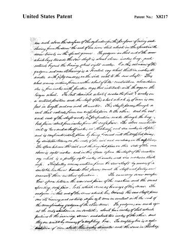
one inch above the surface of the cylinder for the purpose of giving and clearing from the screw the end of an iron shaft which in the operation the screw travels in the spiral groove. The quadrant in that end of the screw which lays towards the saw shaft is about eleven inches long, and extends beyond the bearing about eight inches. On this extension of the quadrant and near its bearing is a beveled cog wheel thirteen inches diameter with fifty one cogs on the side next to the saw shaft. This wheel receives motion from another wheel of like construction, whose diameter is four inches with fourteen cogs that interlock with the cogs on the larger wheel. The last described wheel (as also the first) works in a vertical position and the shaft of this wheel which is of iron is one foot in length and one inch diameter. This shaft passes through a rail that extends from one cross bed piece to the other, and the eastward end of the shaft works in a perforation made through the long bed piece about four inches from the cross piece. The above mentioned rail is two and a half inches in thickness and six inches in depth and is confined in its place by being braced into the cross bed pieces by suitable tenons on the ends of the rail and mortises in the cross pieces. The space between the rail and the long bed piece on this side of the machine is eight inches, and in this space repose the shaft of the smaller cog wheel is a pulley eight inches diameter and six inches in thickness. This pulley receives motion from the saw shaft by means of a suitable leather band that passes round the shaft and pulley and connects them in their operation. The inverting screw occupies the space between the east end piece of the machine and the corresponding cross piece, both which serve as bearings of this screw. The quadrant in that end of the screw which lies towards the saw shaft passes over its bearing and extends so far as to come in contact with the end of the corresponding quadrant of the other screw. The quadrants are made so as at the ends which come in contact, about four inches of that which pertains to the inverting screw, and about two inches of the other, and they are united by means of a coupling box. The coupling box is a cylinder of iron about three inches diameter and the same in thickness.
Page 6.
United States Patent
Patent No.: X8217
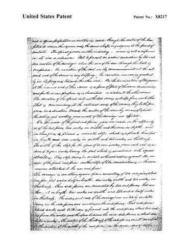
and a square perforation or mortice is made through the centre of the box fitted to receive the square end of the screw shafts or judgmen at the point of contact. The spiral groove on the moving screw is not uniform in its rise or advance. But to prevent an undue concussion by too sudden reaction of the carriage, when the run of the screw through the bolt is completed. The variation of the coil in its commencement at the outward end of the screw is very trifling. The variation increasing gradually in its progress towards the other end. On the termination of the groove at the inward end of this screw is a piece of plate of the same dimension, and for the same purpose as is described in relation to the other screw. The direction of the spiral coil in the two screws is distinct from each other that is commencing at the outward ends of the screws they both progress in a direction towards the centre of the screw by means of which the acting and reacting movements of the carriage are effected.
On the inside of the front end piece grooves are made in the upper side of the bed piece two inches in width and the same in depth, and in these grooves is placed a movable stop, which is a plank three feet in length and six inches in width and two inches in thickness. The width of this stop for the space of seven inches from each end is reduced to four inches leaving the part which is unreduced with square shoulders. This stop comes in contact with and rests against the inside of the front end piece. Another stop of like construction is in the same manner attached to the rear end piece.
The carriage is an oblong square frame consisting of two side pieces which are five feet and a half in length, six inches width and two inches in thickness. These side pieces are connected by two end pieces that are three feet in length, ten inches in width and two and a half inches in thickness. The sides and ends of the carriage are united by suitable tenons on the side pieces and mortices in the end pieces. That side piece which works next to the screw is framed into the end pieces about two inches from the ends and the space between the side side pieces is about six inches in width. The centre of the thickness of the side pieces must correspond to the centre of the width of the end pieces on the under edges of both.
Page 7.
United States Patent
Patent No.: X8217
end pieces and at a line drawn at the center of the width of the side pieces. The end pieces are cut upwards with a square shoulder to the underside of the side pieces and the width of the end pieces is reduced from said shoulder inwards to the ends of the end pieces, so that the under edges of the end pieces on the reduced parts form a level with the under sides of the side pieces. On the outside of both end pieces and extending over the whole of that part which retains the entire width first described is attached two blocks of wood. That are two inches in thickness and six inches in depth. The under edges of these blocks form a level with the under edges of the end pieces, and they may be confined in their places by any kind of suitable fastening. Into the side pieces of the carriage extending from one to the other is inserted a piece of plank called the floor of the carriage. The plank which constitutes the floor is two inches in thickness, and its extent lengthwise of the carriage is about eighteen inches, and the space between the floor and the front end of the carriage is about nine inches. On the upper surface of the floor and extending crosswise of the carriage are three grooves, the fourth of an inch deep and one fourth of an inch wide. The space between the side of the floor towards the front or head of the machine and the first groove is three inches, and the space between the respective grooves is six inches and a half. In these grooves are inserted plates of iron called ratchet. The ratchet project one fourth an inch above the floor and in the projections are teeth resembling those of a splitting saw. The inclination of the teeth being in a direction towards the saw. The first and second ratchet are designed to be used in sawing shingles. The other is used in sawing slats for blinds and that tooth in this may be five eighths of an inch to be varied, however, according to the thickness of the saw. On the outside of the end pieces at the head of the carriage, and about two inches from the side pieces next to the saw, is a square groove one inch and a half in width and half an inch deep extending vertically the whole depth of the end pieces. An iron sliding bolt fifteen inches in length
Page 8.
United States Patent
Patent No.: X8217
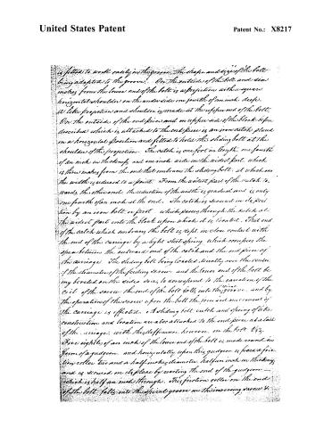
is fitted to work easily in the groove. The shape and size of the bolt being adapted to the groove. On the outside of the bolt and six inches from the lower end of the bolt is a projection with a square horizontal shoulder on the underside one fourth of an inch deep. A like projection and shoulder is made at the upper end of the bolt. On the outside of the end piece and on upper side of the block before described which is attached to the end piece is an iron catch placed in a horizontal position and fitted to hold the sliding bolt at the shoulder of the projection. The catch is one foot in length, one fourth of an inch in thickness, and one inch wide in the widest part, which is three inches from the end that embraces the sliding bolt, at which end the width is reduced to a point. From the widest part of the catch to wards the other end, the reduction of the width is gradual and is only one fourth of an inch at the end. The catch is secured in its position by an iron bolt or pivot which passes through the catch at the widest part into the block upon which it is located. That end of the catch which embraces the bolt is kept in close contact with the end of the carriage by a light steel spring, which occupies the space between the outward end of the catch and the end piece of the carriage. The sliding bolt being located directly over the center of the diameter of the feeding screw and the lower end of the bolt being beveled on the sides so as to correspond to the variation of the coil of the screw, the end of the bolt falls into the groove, and by the operation of the screw upon the bolt the forward movement of the carriage is effected. A sliding bolt, catch and spring of like construction and location are also attached to the end piece at a tail of the carriage, with this difference, however, in the bolt 443, three eighths of an inch of the lower end of the bolt is made round in form of a gudgeon, and horizontally upon this gudgeon is fixed a friction roller two and a half inches diameter, half an inch in thickness, and is secured in its place by riveting the end of the gudgeon — which is half an inch through. This friction roller on the end of the bolt falls into the spiral groove in the inner screw 4.
Page 9.
United States Patent
Patent No.: X8217
by the operation of the screw upon the bolt the inwards movement of the carriage is effected. The carriage thus constructed is fitted to travel upon the iron railway upon four friction rollers that work in mortices made in the under sides of the side pieces of the carriage. The space between the mortices and the end pieces of the carriage is about four inches and the dimensions of the mortices must be adapted to the size and construction of the rollers, whose diameter is four inches and thickness three-fourths of an inch with wrought iron shafts through their centre that are three-fourths of an inch through. The shafts which serve as guide pegs work in semicircular excavations made in the under sides of the side pieces of the carriage at the sides of the mortices. To secure the guide pegs in their places straps of iron with the excavations are attached to the under sides of the side pieces of the carriage by suitable screws or other fastenings. To guide the carriage in its movements on the railway and to facilitate the reduction of friction there are made in the lower part of the end pieces of the carriage at the square shoulders before described and about one inch and half from the bottom square excavations or mortices in which are placed friction rollers two and a half inches diameter and five-eighths of an inch in thickness, through the rollers in round perforations made at the centre iron pins or bolts are passed and on these the rollers revolve. These rollers project roundly beyond the shoulders in the timbers in which they are placed and come in contact with the sides of the iron plates that constitute the railway. A traversing carriage is constructed to operate on the one before described. This carriage consists of a bed piece which is an strong square piece of plank one foot in width and two and a half inches in thickness with a piece of timber framed on each end with tenons on the ends of the bed piece and mortices in the end pieces. The end pieces are three feet in length six inches in width and two and a half inches in thickness. The distance between the end pieces is about four feet. On the upper surface of the carriage and extending its whole length is a groove three inches in width and three-eighths of an inch deep. The space between
Page 10.
United States Patent
Patent No.: X8217
The groove and the side of the carriage next to the saw causes that of the opposite side of three-fourths of an inch. On this groove is written an iron slide one foot and ten inches in length, three inches in width, and four-eighths of an inch in thickness. On the upper side of the bed piece and extending its whole length, directly over the first notch in the floor of the other carriage, as before described, is a groove two inches wide and one-fourth of an inch deep, and in this groove one inch and a half from the backside of the bed piece is a square mortise made through the bed piece, which is the width of the groove one way and three inches the other way. In this groove an mortise is placed an iron sliding gauge which is an iron plate eight inches in length and of the same width and depth as the groove. That part of the plate which opposes the slide is depressed one-fourth of an inch to let the slide pass over it. The transition from the elevated to the depressed part of the plate is made by a shoulder that is vertically square, but horizontally by convex. The shoulder commences on the side of the plate next to the head of the machine, at the side of the groove in which the slide works. But it projects into the groove one inch at its termination. The width of the slide is diminished on the side next to the shoulder sufficiently to accommodate the said projection. Appending from the under side of the plate and within the square mortise above described is a solid square piece of iron the width of the plate one way, one inch and a half the other way, and extending downwards within half an inch of the under side of the bed piece. On the upper side of the gauge and about the center of the width of the slide is a spur which runs about one-fourth of an inch above the surface of the gauge. This spur is fitted to work in a long aperture or mortise made through the slide. The mortise which is four inches in length and half an inch in width, commences about three-fourths of an inch from that side of the slide which is towards the shoulder in the gauge, and passing obliquely towards the other side of the slide, terminates at the above described spur, and the spur enters within the mortise. By an operation of slide upon the spur, in the inverse movement of the under carriage, the spur is forced along in the oblique direction of the mortise, and the upper carriage is thereby drawn towards the saw. The space of one cog or tooth in the teeth beneath, where the
Page 11.
United States Patent
Patent No.: X8217
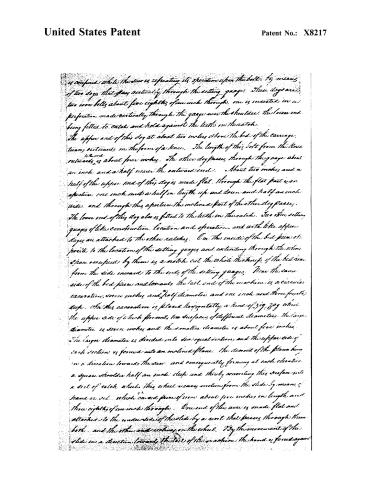
is confined while the saw is effecting its operation upon the bolt, by means of two dogs that pass vertically through the setting gauge. These dogs are two iron bolts about five eighths of an inch through, one is inserted in a perforation made vertically through the gauge near the shoulder, the lower end being fitted to catch and hold against the teeth on the notch.
The upper end of this dog at about two inches above the bed of the carriage, turns outwards in the form of a knee. The length of this bolt from the knee outwards is about four inches. The other dog passes through the gauge about an inch and a half nearer the outward end. About two inches and a half of the upper end of this dog is made flat. Through the flat part is an aperture, one inch and a half in length up and down and half an inch wide, and through this aperture the inclined part of the other dog passes.
The lower end of this dog also is fitted to the teeth on the scale. Two other setting gauges of like construction, location and operation, and with like upper dogs are attached to the other scales. On the inside of the bed piece opposite to the location of the setting gauges and extending through the whole space occupied by them is a notch cut the whole thickness of the bed from the side inward to the ends of the setting gauges. Near the same side of the bed piece and towards the tail end of the machine is a circular excavation, seven inches and half diameter and one inch and three fourths deep. In this excavation is placed horizontally a kind of zig zag wheel, the upper side of which presents two surfaces of different diameters. The large diameter is seven inches and the smaller diameter is about five inches. The large diameter is divided into six equal sections, and the upper side of each section is formed into an inclined plane. The diameter of the plane being in a direction towards the saw, and consequently forming at each elevation a square shoulder half an inch deep and thereby converting this surface into a sort of ratchet wheel. This wheel moves motion from the slide by means of hand or set, which carries piece of iron about five inches in length and three eighths of an inch through. One end of this arm is made flat and attached to the underside of the slide by a nut that passes through them both, and the other end revolves on the wheel. By the movement of the slide in a direction towards the tail of the machine the hand is forced again
Page 12.
United States Patent
Patent No.: X8217
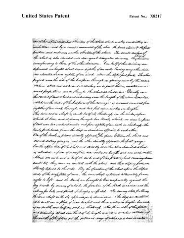
one of the above described shoulders of the wheel which makes one sixth of a revolution, and by a counter movement of the slide the hand returns to its first position and embraces another shoulder of the wheel. The annular surface of the wheel is also divided into six equal triangular divisions, the divisions corresponding to those of the other divisions. One half of the divisions are depressed in height about seven eighths of an inch leaving every other division elevated seven eighths of an inch above the depressed parts. The wheel projects over the side of the bed piece through an opening made by the excavation, about one inch and it revolves on a pivot that is inserted in a round perforation made through the wheel at the centre. Directly over the centre of said wheel and extending over the length of the above described notches in the side of the bed piece of the carriage is a round iron rod five eighths of an inch through, and two feet nine inches in length. This iron rod or shaft is sunk half its thickness in the timber upon which it bears, and it passes through two knobs which are circular pieces of cast iron two inches diameter and five eighths of an inch in thickness. The knobs protrude from the shaft in directions opposite to each other. One of the knobs is placed directly opposite the space between the third and second setting gauges, and the other directly opposite the first gauge. On the upper side of the shaft and directly over the above described wheel is attached a piece of iron plate six inches in length and one inch width. About an inch and a half at each end of this plate is bent curving downward till they come in contact with the wheel, and these sloping parts are obliquely tapered to the ends. By the operation of the wheel upon the sloped ends of the edge plate of iron, the iron shaft is turned alternately from right to left, and the knobs are brought to bear reciprocally against the dog blocks by means of which the position of the block is varied and the setting for bolts and points of shingles is effected. In sawing slats for laths, the iron shaft with its appendages is dismissed. The dogs are constructed to work on a plate of iron two feet and three inches in length, two inches in width and half an inch in thickness. In the middle of the plate and extending about one third of its length is a semi circular indentation of the width of the plate on the outward edge of which is a semi circular
Page 13.
United States Patent
Patent No.: X8217
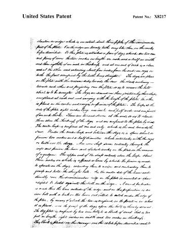
elevation or ridge which is in extent about three fifths of the semicircular part of the plate. On this ridge are twenty teeth, very like those on the racks before described. To this plate is attached a pair of dogs which are two curved pieces of iron thirteen inches in length, one inch and a half in width and three eighths of an inch in thickness, and at one end of each is a claw, and at the other end extending about five inches from the end, are cogs or teeth, the part occupied by the teeth being straight. The dogs are placed on the plate with the concave sides towards the saw. The claws inclining towards each other and projecting over the plate so as to receive the bolt which is to be wrought. The dogs are secured in their position by three loops, one placed at each end and ranging with the length of the plate, the other is placed in the centre and ranges in width of the plate. The loops at the ends of the plate eight inches long, one inch and half wide and one fourth of an inch thick. These are turned down at the ends so as to elevate them above the thickness of the dogs, and are confined to the plate by rivets. The centre loop is confined at one end only, which is the end towards the saw. Under the centre loop and between the dogs is a spur wheel or pinion two inches and a half diameter which interlocks with the cogs or teeth on the dogs. An iron shaft passes vertically through the loops and pinion the lower end of which works in the plate in the manner of a gadgun. The upper end of the shaft extends above the loops about three inches on which is affixed a lever by which the pinion is made to operate on the dogs, extending them to receive and contracting them to grasp and hold the shingle bolt. On the under side of the lower and directly over the semicircular ridge on the plate is inserted a spur adapted to hold against the teeth on the edge. A second perforation is made thru the lower outside of the edge and in this perforation is an iron bolt with a hook in the lower end fitted to catch under the edge of the plate, by means of which the lever is confined in the position in which it is placed, and the grasp of the dogs upon the bolt is thereby secured. The dog plate is confined by two iron bolts to a block of wood that is two feet in length, eight inches in width and two inches in thickness. This block is placed on the carriage on the catch before described and to
Page 14.
United States Patent
Patent No.: X8217
Complete construction of the block a piece of plank is attached to the underside of the piece already described extending the whole length of the notch, and the whole depth of the carriage. The block is secured in its position by a screw bolt which extends outward from the upper side of the bed piece of the carriage and passes through the side piece of the block, and passes through the side pieces of the blocks, at the centre of its length where a suitable nut is fixed on the screw and upon this screw as upon a pivot. The changes of the position of the dog blocks and consequently of the shingle belt are made, whereby through the operation of the knobs upon the block as before described, the alternate settings for the belly and points of the shingle is effected. On the underside of the bed piece of the upper carriage extending the whole width are grooves made to accommodate the catenaries in the floor. Into that end piece of the carriage which lies towards the tail of the machine are passed two screw bolts that press against two small pieces of iron plate which are placed in cavities made in the side of the end piece, and by means of these screw bolts the carriage is kept from working too loosely. The dog plate must be elevated before the belt is placed in the dogs, by means of which the belt will settle on the carriage as the width is diminished. A set of dogs different from those before described are constructed to be applied in the use of this machine, if preferred. These dogs are fitted to work on a plate of the same size and construction of the one before described, excepting the semicircular ridge with teeth. The dogs are two pieces of iron, each about six inches in length, one inch and a half in width, and three eighths of an inch thick. On one end of the dogs are claws fitted to grasp and hold the shingle belt. Two round perforations are made through each of the dogs, one near the centre of their length, the other near the end. They are attached to a plate by iron bolts passed through them, and the plate at the perforations made at the centre. A lever is fixed on and confined to the plate by a screw bolt that passes through the lever and the plate at the centre with a thumb screw on the top of the bolt. Upon this screw bolt the lever operates, as upon a pivot. The dogs are connected with the lever by two straps of iron.
Page 15.
United States Patent
Patent No.: X8217
which pass from them to the lever, and are confined by suitable rivets, all of which must work easily in the positions in which they are mounted. The end of one strap is attached to the lever in front and the other in rear of the pivot on which the lever works.
The knobs which operate upon the dog blocks must be placed nearer together for short bolts than for long ones. The specific new and useful improvements herein before described and claimed by me as the first inventor are the following. 1st The mode of moving the carriage by screw. 2nd The mode of reducing friction and guiding the carriage in its movements by the application of friction rollers. 3rd The particular construction of the dogs and the mode of applying them to the bolt. 4th The particular mode of changing the position of the bolt so as to saw different lengths. 5th The particular mode of keeping the bolt firmly on the carriage by means of elevating the dog plate when the bolt is first applied. 6th The particular mode of setting for the shingles to be sawed.
The improvements described in the foregoing specification, give to the machine advantages over other simple machines in equality and regularity of motion, consequently less liability to injury or derangement of the parts by concussion.
In testimony that the foregoing is a true specification of my said improvement, I have hereunto set my hand the twenty second day of February in the year of our Lord one thousand eight hundred and thirty four
Isaac Drake
Test. Witnesses
Wm. Fiske
James Morrell
(6258 2754)
Published accounts: journal notice
Notice in the monthly list of patents, with remarks
Journal of the Franklin Institute, new ser., vol. 14 (1834), p. 406 · View the page
40. For a Machine for Sawing Shingles and Blind Slats; Isaac Drake, Minot, Cumberland county, Maine, May 24.
Remarks. The specification of this machine would, of itself, form a small volume, from which we will abstract the claims only. "The specific and useful improvements hereinbefore described, and claimed by me as the first inventor, are the following: 1st. The mode of moving the carriage by screws. 2d. The mode of reducing friction, and guiding the carriage in its movements by the application of friction rollers. 3d. The particular construction of the dogs, and the mode of applying them to the bolt. 4th. The particular mode of changing the position of the bolt, so as to saw different lengths. 5th. The particular mode of keeping the bolt firmly on the carriage, by means of elevating the dog plate, when the bolt is first applied. 6th. The particular mode of setting for the thickness of the shingles, &c. to be sawed."
About this record
- Patentee
- DATAMP
- Date
- the Name and Date index of patents, DATAMP, USPTO records
- Invention
- DATAMP
- Listed in
- the Name and Date index of patents, DATAMP, USPTO records, Jim Shaw's X-patent list, the Journal of the Franklin Institute, Burke's List of Patents (1847)
- Burke's 1847 Patent Office list gives the same patent.