

Drawings and documents
National Archives restored drawings: drawing
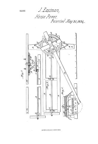
J. Eastman's Patent Drawing for a Machine for the Application of Horse Power

National Archives, Restored Patent Drawings (Record Group 241) · Full-size scan at the National Archives · Catalog record
Show the text on the drawing Hide (59 words)
Words on the drawing as machine-read by the National Archives; not checked. Useful mainly for searching.
POWE / Our / 185, Mechanical Motors! / $2. / Forse-power,s Gears. er / J.EASTMAN'S o / HORSE POWER. / CLASSIFICATION / 8228- / Patented May the 31ˢᵗ 1834 / Cat may 31-1834 / LIV ISION. / Sohn Martineau ladministrator, / 11 / in / GL / Fig. 2. / Fig.1. / 70 / O H / b. / Fig. / 3. / nb / Scale of feet and parts of ft.
USPTO scan
The patent as scanned by the USPTO
-
 Page 1
-
 Page 2
-
 Page 3
-
 Page 4
-
 Page 5


U.S. Patent and Trademark Office · Google Patents
Show the transcription Hide (1,539 words)
Machine transcription (LightOnOCR) of the pages as scanned by the USPTO, most of them the handwritten copies made when the records were restored after the 1836 fire. Not checked; it can misread handwriting, so compare it with the scan.
Page 1.
8228X
J. Eastman,
Horse Power.
Patented May 31, 1834.

A.M. PHOTO-LITHO. CO. N.Y. (OSBORNE'S PROCESS)
Page 2.
8228 X
May 31, 1834
John Martinian, New Hampshire
Letters Patent
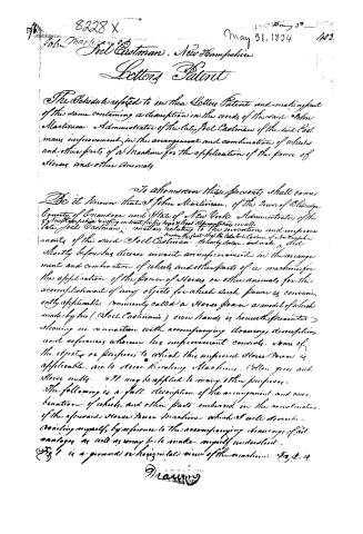
The Schedule referred to in these Letters Patent and making part of the same containing a description in the words of the said John Martinian, Administrator of the late Joel Eastman of the said Eastman's improvement in the arrangement and combination of wheels and other parts of a Machine for the application of the power of Horses and other Animals.
To whomsoever these presents shall come
Be it known that I, John Martinian, of the Town of Oldridge, County of Orange and State of New York, Administrator of the late Joel Eastman, do hereby declare that the late Joel Eastman of New Hampshire, shortly before his decease, invented an improvement in the arrangement and combination of wheels and other parts of a machine for the application of the power of Horses or other animals for the accomplishment of any objects for which such power is conveniently applicable, commonly called a Horse Power, a model of which made by his (Joel Eastman's) own hands is herewith presented showing in connection with accompanying drawings, description, and references wherein his improvement consists, some of the objects or purposes to which this improved Horse Power is applicable, are to drive threshing Machines, Cotton gins and Stone mills. It may be applied to many other purposes.
The following is a full description of the arrangement and combination of wheels and other parts embraced in the construction of the aforesaid Horse Power Machine which I will describe, referring myself by reference to the accompanying drawings of said machine as well as may be to make myself understood.
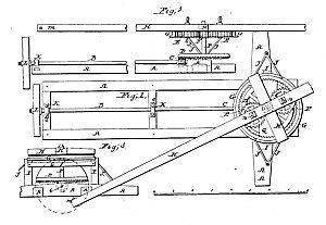
Fig 1 is a ground or horizontal view of the machine. Fig 2 is
Drawing
Page 3.
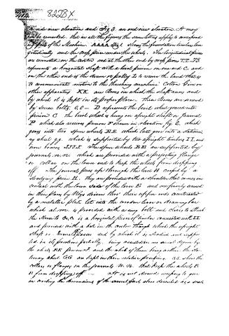
a side view elevation and Fig 3. an end view elevation. It may here be remarked, that in all the figures the same letters apply to corresponding parts of the Machine. AAAA Fig 1. shows the foundation timbers longitudinally and the cross pieces under the wheels. The longitudinal pieces are connected in the center and at the other end by cross pieces T.T. T3. represents a horizontal shaft with a bevel pinion on one end C, and on the other end is the drum or pulley E to receive the band that is to communicate motion to the threshing machine Cotton Gin or other apparatus K.K. are Boxes in which the shaft runs and by which it is kept in its proper place. These Boxes are secured by screw bolts. O.O. — D represents the bevel wheel geared into pinion C. The bevel wheel is hung on an upright shaft or journal P which also receives pinion E shown in elevation fig 2, which gears into two spun wheels B.B. which last gear into a stationary wheel g.g. which is supported by two upright timbers I.I. and iron braces J.J.J.J. The spun wheels B.B. are supported by journals, N.N. which are provided with a projecting flange or collar on the lower end to keep the wheels from dropping off. The journals pass up through the lever H supported by a straining piece LL. They are provided with a shoulder that comes in contact with the lower side of the lever H and are firmly secured in their places by keys driven thru their upper ends, counteracted by a metallic plate let into the wooden lever or straining bar which at one end is provided with a ring bolt and clevis to attach the stone to O.O. is a horizontal piece of timber connected with I.I. and provided with a hole in the center through which the upright shaft or journal P passes and by which it is steadied and supported in its position partially, being assisted in no small degree by the abutting ends pinions and the abut of them being within the stationary shaft G.G. are kept in their relative positions. S.S. where the collars or flanges on the journals N.N. that keep the wheels B.B. from dropping off — It is not deemed necessary to give in writing the dimensions of the several parts above described as a man
Page 4.
8228X
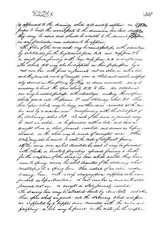
is appended to the drawing, which will readily explain. nor is it proper to limit the several parts to the dimensions here laid down; they may be varied and should be adapted to the amount of power in any particular case intended to be applied.
The plan of the wood works may be varied perhaps with advantage by substituting for the longitudinal pieces A A and cross pieces T T a single piece forming with large cross pieces A A a simple cross. The wheels E E may also be supported in their proper place by a cast iron bar, with pins or journals cast on solid or with a hole and the journals made of wrought iron or steel and inverted and properly secured in their places by keys or screws and nuts. nor is it necessary to limit the open wheels E E to two. Any additional one may be added perhaps with advantage, making three open wheels geared into the pinion F and stationary wheel S S. These three open wheels may be hung on three arms connected at the centre and by a circular rim corresponding with the solid part of the stationary wheel S S. To each of the arms a journal may be cast on solid, or be provided with a hole and have a wrought iron or steel journal inverted and secured as before observed or the whole may be made of wrought iron. Other details may also be varied to suit the taste of different persons.
If the cross rim as last described be used it may be provided with cheeks or brackets projecting upwards forming a birth for the reception of the drawing lever which would thus have room to swing across the whole diameter of the stationary wheel, constituting it a spring lever. When instead of an entire wooden drawing lever, with a cross sliding piece supplied with iron journals as before described. A cast iron bar is used with solid journals cast on, or wrought or steel journals inverted.
The drawing lever may be attached thereto by iron bolts and when these open wheels are geared into the stationary wheel and pinion supported by a trippler arm connected with the centre and springing, a hole may be formed in the centre for the reception
Page 5.
406 8228 X
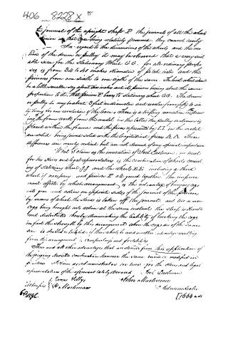
the journal of the upright shaft P. The journals of all the wheels
pinion in that case being relatively pressed. They cannot easily
In regard to the dimensions of the wheels and the mo
tion of the drum or pully it may be observed that a very suit
able size for the stationary wheel G G. for all ordinary purposes
is from 34 to 40 inches diameter of pitch axle and the
pinions from one sixth to one eighth of the same. The bird wheel should
be a little smaller say about six inches and its pinion being about the same
proportion to it, that pinion E bears to stationary wheel G G. The drum
or pully L may be about 3 feet in diameter and revolve from fifty to six
ty times for one revolution of the lever. There is a trifling variation in draw-
ing the frame work from the model. In the latter the pully or drum is
placed within the frame and the piece represented by I I in the model
are solid being joined solid with the longitudinal pieces A A. These
differences are merely noticed but are not deemed of any special importance.
What is claimed as the invention of Joel Eastman, in trust
for his heirs and legal representatives is the combination of wheels consist-
ing of stationary wheel G G and the wheels E E including a third
wheel if necessary, and pinion E all geared together. The improve-
ment effected by which arrangement is the advantage of bringing cogs
into gear and action on opposite sides of the journal of the pinion
by means of which the strain is taken off the journal, and two or more
cogs being brought into action at the same instant the stress is divided
and distributed thereby diminishing the liability of breaking the cogs
in fact the strength by this arrangement when the cogs are of the same
size is doubled or tripled if three wheels be used another advantage resulting
from this arrangement is compactness and portability.
There are all other advantages that are derived from this application of
the foregoing described combination however the same broad or modified in
particular as herein described may be used for the heirs and legal
representatives of the aforesaid Joel Eastman
James Kellys
Witness & D. A. Hartman
672156.
John A. Hartman
Administrator
[7664 and]
Published accounts: journal notice
Notice in the monthly list of patents, with remarks
Journal of the Franklin Institute, new ser., vol. 14 (1834), p. 410 · View the page
50. For a Horse Power; invented by Joel Eastman, late of New Hampshire, deceased. Patented by his administrator, John Martineau, of Eldridge, Onondaga county, New York, May 31.
Remarks. This is a very ingeniously contrived apparatus, the invention of a gentleman whose talent for inechanics was of no ordinary kind, and who, had he lived, would, probably, have found but few equals in a department in which our citizens may be said to excel. His premature death was a real loss to his country, whilst those estimable moral qualities by which he was distinguished, left a void, not easily filled, in the bosoms of those who knew him intimately. In this machine there is a stationary wheel placed horizontally on a suitable bed, or frame. This wheel has teeth on its inner rim, pointing towards its centre. The lever by which the horse is to draw, crosses the upper side of this fixed wheel, and has, on its lower side, two (or three) smaller wheels, which drop within, and gear into, the teeth of the fixed wheel, and also into a pinion standing between them, on a shaft in the centre of the fixed wheel. On the lower end of this central shaft there is a crown wheel which gears into, and drives a pinion upon, a horizontal shaft, through which motion is to be given to any machinery. The claim is to the stationary wheel, combined with the smaller wheels which gear into it, and to the pinion in the centre; "the improvement effected by which arrangement, is the advantage of bringing cogs into action on opposite sides of the journal of the pinion, by means of which the stress is taken off the journal, and two or more cogs being brought into action at the same instant, thestress is divided and distributed; thereby diminishing the liability of breaking the cogs; and, in fact, doubling the strength by this arrangement where the cogs are of the same size, and trebling it if three wheels are used. Another advantage resulting from this arrangement, is compactness and portability. These and all other advantages that are derived from this application of the foregoing described combination, however the same may be modified in practice, is claimed in trust for the heirs and legal representatives of the aforesaid lately deceased Joel Eastman."
DATAMP: illustration
Illustrations from DATAMP

DATAMP (Directory of American Tool and Machinery Patents), via the Internet Archive · Archived DATAMP page
About this record
- Patentee
- DATAMP
- Date
- the Name and Date index of patents, DATAMP, USPTO records
- Invention
- DATAMP
- Listed in
- the Name and Date index of patents, DATAMP, USPTO records, Jim Shaw's X-patent list, the Journal of the Franklin Institute