

Drawings and documents
National Archives restored drawings: drawing
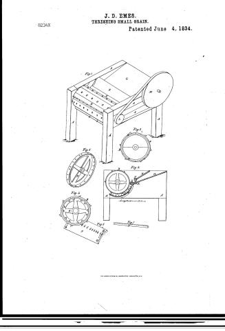
James D. Emes' Patent Drawing for a Machine for Threshing Small Grain

National Archives, Restored Patent Drawings (Record Group 241) · Full-size scan at the National Archives · Catalog record
Show the text on the drawing Hide (135 words)
Words on the drawing as machine-read by the National Archives; not checked. Useful mainly for searching.
11 / 130. THRASHING. / [] / Thrashing Machines. / A. Cylinder Machines. / Eylio / Einlered. James L. Emes, Emes / Vol.19.72.433. / $350 / Threshing Small Grain / Patented 4.June 1834, / 8234-X / division. / Fif.5, / Fig.1. / Fufe. / M. / FL / Figh. / Fide3. / 11 / References, / Fifi. Perspective view. / VV N 4) Fif6 IM / Fid 3 endview of cylinder. Fighend view of cylinder / Patent Office Mar:17. B42. / with wooden head removed, Fif5, castirowhead, / Made under they direction of the Commissome / Fid,6. segment of laging Fight barof concave, / A. frame B. cylinder. E.concare, D, wroughtion / of Patents in conformity with act of Cougrefs 3March1837, / roller, E. lower feed roller, F. upperfecd roller. G."pitch Ward, / Hang Lillinorth / Hswinteing hitch board, I.barsofcencave, K iron heads of cylinder / I. pulley on cylinder. M. driving wheel, Milading. / Commission of Patents;
USPTO scan
The patent as scanned by the USPTO
-
 Page 1
-
 Page 2
-
 Page 3
-
 Page 4
-
 Page 5
-
 Page 6


U.S. Patent and Trademark Office · Google Patents
Show the transcription Hide (1,852 words)
Machine transcription (LightOnOCR) of the pages as scanned by the USPTO, most of them the handwritten copies made when the records were restored after the 1836 fire. Not checked; it can misread handwriting, so compare it with the scan.
Page 1.
8234X
J. D. EMES.
THRESHING SMALL GRAIN.
Patented June 4, 1834.
Fig. 1.
Fig. 3.
Fig. 5
Fig. 2
Fig. 4
Fig. 6
Fig. 7
THE NORRIS PETERS CO., PHOTO-LITHO., WASHINGTON, D. C.
Page 2.
June 4, 1834
James D. Emery
Letters Patent
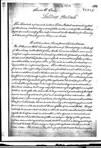
The Schedule referred to in these Letters Patent and making part of the same, containing a description in the words of the said James Dyer Emery himself of his improvement in the Machine for threshing all kinds of small grain, rice, and seeds.
To all to whom these presents shall come.
Be it known that James Dyer Emery of Lansingburg in the county of Rensselaer, in the state of New York, have invented a new and useful improvement in threshing all kinds of small grain, rice and seeds, and that the following is a full and exact description of the construction and operation of the said invention (or machine) as invented or improved by me. This machine is constructed by a frame, the supporting side pieces of which are about ten inches wide and three inches thick and a corresponding frame of strength sufficient to firmly support the machinery to be attached, graduated by the size and length of the cylinder, the best proportion of which (the cylinder) is twenty-two inches long and in diameter or thirteen inches, but may vary (to produce a good effect) from one foot to three in length, the diameter to be governed & graduated by the length never running above two feet nor sinking below six inches. The cylinder is formed of cast iron, having three heads cast and turned to a perfect circle, these heads having a broad flange from one to two inches wide and about three eighths of an inch thick. Through which, holes should be drilled or slots cast to admit a bolt from two eighths to half an inch in diameter, with a square or round head counter sunk in the bands of the covering or lacing of the cylinder, a fine screw being cut on each bolt to receive a strong nut, sufficient to hold the covering or lacing of the cylinder which are cast iron, also. The holes in the flange of each head to be in number making
Page 3.
making in all (if the cylinder is formed with three heads) (which is better) thirty six or if with two heads, twenty four; the heads which will be about ten inches in diameter should be set, the two end heads (if three are used) about three quarters of an inch in from the end of the east iron lagging, which should be about three sixteenths of an inch thick with strips or bands one and a half inch wide, and half inch thick to admit the bolt head for eighths of an inch square or round, and the third head placed in the center, if two heads only are used, they they should be placed upon the cylinder shaft six inches in from the end of the lagging or covering of the cylinder, leaving about ten inches space on the inside between the heads, the strips or bands of the east iron lagging should in all cases correspond with the heads to which they are to be attached and to prevent the straw and grain from getting into the cylinder when in motion a wooden head about three quarters of an inch thick is to be neatly fitted in flush with the ends of the lagging and confined to them on the shaft by four wood screws in each, entering through holes drilled in the lagging to receive them. The holes to receive the bolt in the flange of the heads may be topped after drilling and a screw cut therein to answer in lieu of a nut, but bolts and screws having heavy nuts, on the under side and drawing the lagging firmly to the head is best. The covering or laps of the cylinder are divided into equal parts coming together with locked or bevel joints the edges pushing each other from one quarter to half an inch, having a projection from the lagging for a bevel beater and forming the outer surface and east solid with it. Three quarters of an inch raises more or less and about three quarters of an inch wide at the base having a brace one quarter of an inch the surface of which beater is grooved one quarter or half inch deep leaving opposing mitre edges. The joint edge being lower about one fourth of an inch or one eighth of an inch (in proportion to the diameter of the cylinder) than the back or following edge of each beater. Notches being east or filed diagonally across the beater beginning at or near the center of the length of the cylinder so as to spread the beam from the center nearly to the ends and return.
Page 4.
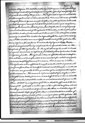
return it again toward the centre by its progress in the operating, thrashing under the cylinder, producing the effect of completely hulling and bruising the grain. The different ways in which this beater may be used is thus described, to secure the same operation: it may be placed square across, lengthwise of the cylinder in the centre of each lacing or nearly back to its joint, and being so may have, holding the same bevelled surface, points of beaters running diagonally from one end to the other of the cylinder to the centre; on the surface, or from one to two inches from each end to the centre or bevelled from each end running in about two inches having a straight bar in front or running one or two inches more or less from the ends of the cylinder then running in a spiral form round on the lacing and vice versa—each arrangement being confined to an equal division on the surface of the cylinder. Or the cylinder may be cast in bands of equal divisions, and firmly jointed together by bristles, locks or square joints. The cylinder when completed should be a modification roller, and be suspended over a cone or for all kinds of grain, and used excepting flax and broomcorn. Then a cone is better. The cylinder when applied to any power should be so geared as to give from fourteen to twenty hundred revolutions per minute, and set from one quarter to three quarters of an inch from the surface of the cone. The cone is formed first of a single cast or wrought iron roller, from one and a half to two inches in diameter, with grooves bevelled to the centre on one side and cast square on the other, so that in every turn of it there shall be opposed to the surface of the cylinder a mitre edge with a spiral surface, also cast beveling on one side and square on the other, and continuous to accommodate the progress of the steam which should be a motion of about one to five or six of the running surface of the cylinder. This roller is followed to form, continue, and finish, the cone or plate or bar of wrought or cast iron, made or cast in one division, or formed or turned in or otherwise firmly attached to the frame of the machine, the degree of which should be about three sixteenths of an
Page 5.
of an inch or one fourth of an inch from the surface of the roller described and from each following edge of the slats or bars of the cone above and should be continued with a sufficient throat or opening to discharge the threshed straw, throwing up a slow or gradual ascent after it leaves the outer plane surface of the cylinder, these slats or bars are formed of iron cast or wrought about one inch deep and three fourths of an inch wide the surface of each slat or bar being thus made from the first edge to the following a bevel groove should be cut leaving the next metric edge at least three eighths of an inch deep across which should be cut or cast eontra diagonal Notches, the object of which is to thresh the under side of the straw as turned and operated upon by the motion and surface of the cylinder above it the straw is fed to the cylinder by means of a hopper or pitah board hinging directly between it and running free one or two rollers from three to four inches in diameter, set on the same base line of the center of the commencement of the cone above and driven by leather belts from a sheen or wheel on the end of the cylinder shaft, and like sheers or wheels on the end of each roller, or from the shaft of the driving wheel. The driving wheel should be about four or five feet in diameter and four inches wide when attached to a portable horse gearing, directly over the lower feeding roller, above described is placed a pitch board hanging upon a pint hinge or swivel to which is attached a free roller moved by nothing but the progress of the straw or unthreshed grain and held upon it by spring sunk in the side pieces of the hopper or feeding box or by special springs on the upper side. The cylinder shaft should be made of close strong wrought iron at least one and a half inch square or round the bearings of which should be turned perfectly round and smooth to admit friction bushes even eighths to one and a half inch to encircle the axle of the cylinder shaft, which may be made of cast iron with flanges projecting out from the outside of the case two or three inches and half an inch thick through which holes should be drilled to admit bolts to keep the box steady when rising from its stationary position produced by the motion of the cylinder, on the shaft of the cylinder
Page 6.
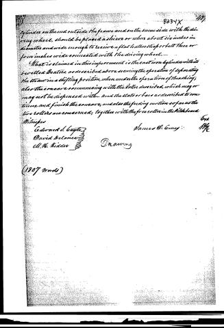
cylinder on the end outside the frame and on the same side with the driving wheel, should be placed a sheave or wheel about six inches in diameter and wide enough to receive a flat leather strap or belt three or four inches wide connected with the driving wheel.
What is claimed in this improvement is the cast iron cylinder with its levelled Beaters, as described above securing the operation of separating the straw in a shifting position, when under the operation of threshing; also the cone are commencing with the roller described, which may or may not be dispensed with and the slats or bars as described to continue and finish the cone are, and also the feeding motion so far as the two rollers are concerned; together with the free roller in the ditchboard
Witnesses
Edward S. Bugte
David Belance
W. W. Hiddes
James D. Coney
(1807 words)
Published accounts: journal notice
Notice in the monthly list of patents, with remarks
Journal of the Franklin Institute, new ser., vol. 15 (1835), p. 28 · View the page
6. For a Thrashing Machine; James D. Emes, Lansingburgh, Rensselaer county, New York, June 4.
Remarks. The claims set up in this case are to "the cast iron cylinder, with its bevilled beaters, as described, securing the operation of separating the straw in a shifting position, when under the operation of thrashing. Also, the concave commencing with a roller, which may, or may not, be dispensed with; and the slats or bars as described, to continue and finish the concave; and also the feeding motion, so far as the two rollers are concerned, together with the free roller in the pitch board." We have heard of such a thing as "darkening council with words without knowledge;" and in reading the specification, one might be tempted to believe that it was intended as an illustration of the process in the mind of the writer of the foregoing quotation. The description of this machine is a story of great length, consisting of many well-filled pages, over which we have carefully looked, in the hope that we might discover a discovery; but, alas! all to no purpose. We have, it is true, met with some new terms, the meaning of which we have guessed at by the context; but as to any thing novel in the machine, if it exist, it is too recondite, or transcendental, for us.
About this record
- Patentee
- DATAMP
- Date
- the Name and Date index of patents, DATAMP, USPTO records
- Invention
- DATAMP
- Listed in
- the Name and Date index of patents, DATAMP, USPTO records, Jim Shaw's X-patent list, the Journal of the Franklin Institute, Burke's List of Patents (1847)
- Burke's 1847 Patent Office list gives the same patent.