

Drawings and documents
National Archives restored drawings: drawing
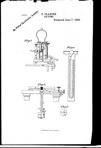
T. Claxton's Patent Drawing for an Air Pump

National Archives, Restored Patent Drawings (Record Group 241) · Full-size scan at the National Archives · Catalog record
Show the text on the drawing Hide (50 words)
Words on the drawing as machine-read by the National Archives; not checked. Useful mainly for searching.
*&-PNEUMATICS. / AIR & GAS PUMPS, / Mechanical / T. CLAXTON / Fig.L / air Pump / CL ASSICI I TION / Patented "1th June. 1834 / 8240 - X / DIVISION. / no model / Elg.4. / Wh / 70 / "5 / Fig.2. / of / mum / S. / Fig.3 / 40
USPTO scan
The patent as scanned by the USPTO
-
 Page 1
-
 Page 2
-
 Page 3
-
 Page 4
-
 Page 5


U.S. Patent and Trademark Office · Google Patents
Show the transcription Hide (1,513 words)
Machine transcription (LightOnOCR) of the pages as scanned by the USPTO, most of them the handwritten copies made when the records were restored after the 1836 fire. Not checked; it can misread handwriting, so compare it with the scan.
Page 1.
8240X
No Printed Specification Available
T. CLAXTON.
AIR PUMP.
Patented June 7, 1834.
Fig. 1
Fig. 2
Fig. 3
THE NORRIS PETERS CO., PHOTO-LITHO., WASHINGTON, D. C.
Page 2.
270 6-7-1834 8240 2493
(Simothy) Blaxton, Boston, Massachusetts.
Letters Patent.
Dated June 7th 1834.
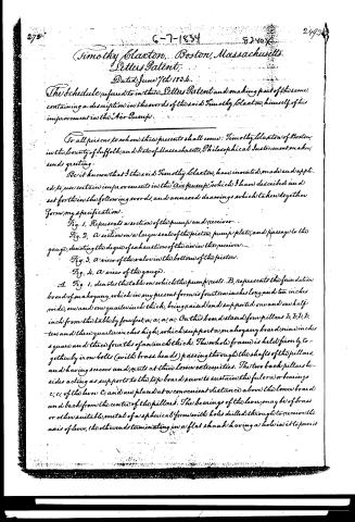
The Schedule referred to in these Letters Patent and making part of the same, containing a description in the words of the said Timothy Blaxton, himself, of his improvement in the Air Pump.
For all persons to whom these presents shall come: Timothy Blaxton of Boston, in the county of Suffolk, and State of Massachusetts, Philosophical Instrument maker, sends greeting.
Be it known that I the said Timothy Blaxton, have invented, made and applied to use certain improvements in the "air pump" which I have described and set forth in the following words, and annexed drawings which taken together form my specification.
Fig. 1. Represents a section of the pump and receiver.
Fig. 2. A section on a larger scale of the piston, pump plate, and passage to the gauge, denoting the degree of exhaustion of the air in the receiver.
Fig. 3. A view of the valve in the bottom of the piston.
Fig. 4. A view of the gauge.
A. Fig. 1. denotes the table on which the pump rests. B, represents the foundation board of mahogany, which in my present form is fourteen inches long and ten inches wide, one and one quarter inch thick, being raised and supported one and one half inch from the table by four feet, a, a, a, a. On this board stand four pillars b, b, b, b, ten and three quarter inches high, which support a mahogany board nine inches square and three fourths of an inch thick. The whole frame is held firmly together by iron bolts (with brass heads) passing through the shafts of the pillars, and having screws and nuts at their lower extremities. The two back pillars besides acting as supports to the top board serve to sustain the fulcrum or bearings c, c, of the lever C, and are placed at a convenient distance above the lower board and back from the center of the pillars. The bearings of the lever may be of brass or other suitable metal of a spherica form with holes drilled through to receive the axis of lever, the other end terminating in a flat shank having a hole in it to permit
Page 3.
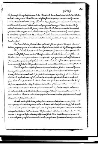
the passage through of the iron bolt. This shank has a broad shoulder behind the bolt which rests against the pillar (made flat for the purpose) and is secured by a screw and nut at its other extremity. The lever C, is of cast iron or other suitable metal, open in the centre to admit the barrel and gauge, and having at its ends a handle by which the operator puts the pump in action. To the lever is connected two rods by joints at their upper ends, the lower ends of which are attached by similar joints to the bottom of the barrel D, so that when the lever is moved the barrel is allowed to traverse upwards and downwards between the guide rods d, d, in a perpendicular direction.
The barrel D, is a plain hollow cylinder of brass open at top and closed at bottom, properly ground out to receive the piston and to be air tight during its motions.
The guides d, d, are parallel steel rods properly secured at their tops into the upper board of the frame, and at their opposite ends into the lower board of the same. The barrel has at its top and bottom, two flanches or projections to which fluted pieces of composition of the length of the barrel, are attached. These fluted pieces of composition are accurately fitted to the guide rods so as to ensure the rectilinear motion of the barrel.
On the top board of the frame a triangular brass plate, c, is secured by screws passing through it into nuts on the underside of the board. From the bottom of this brass plate c, a round rod, f, projects terminating in a piston g. A small hole is drilled through the centre of this rod and piston, through which the air is conducted from the receiver to the barrel. At the lower end of the piston there is a valve h, (of the form represented in Fig. 3.) to prevent the return of the air into the receiver. The air, when the barrel is raised escapes from the same through the passage i, which is a circular hole bored in the piston, terminating at the top in a small seat, on which rests a valve k. The said valve k, during the downward motion of the barrel is closed by the pressure of the external air.
In the centre of the triangular plate, c, is secured the brass receiver plate l. To intercept any dirt, broken glass or other substances which might accidentally fall into the hole in the top of the receiver plate, the inside of the piston rod, at its connection with the triangular plate c, is hollowed out in the form of a small chamber into which a small brass cup m, is dropped, before attaching the ground plate. The sides of this cup are grooved to admit the passage of the air around it, and it may be easily removed at any time should
Page 4.
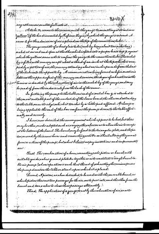
any extraneous matter fall into it.
A tube, N, connects the receiver with the gauge terminating at its end in a "gallon" (of the kind invented by Professor Hayne) by which the gauge is secured. A screw O, for the admission of air is placed on the top of the connection tube.
The gauge consists of a bent glass tube (each leg being about two inches long) sealed at one end and open at the other, which is fitted into a proper brass cup P, against which the gallon screw acts to confine the gauge to the connection tube. The sealed leg is filled with mercury except about a third of an inch at the top, which is occupied by a portion of air, the mercury extending about an inch upwards from the end of the tube into the opposite leg. A communication being formed as before mentioned between the upper surface of the mercury and receiver, the degree of exhaustion in the receiver is denoted by the exhaustion of air in the sealed leg of the gauge, and may be read off from the index scale from the back of the same.
In fastening the pump to the table one end of a metal bar q, is attached to the most suitable part of the underside of the lower board, the other end extending to the table near its edge, which it touches by a little pad affixed. A clamp r, being applied to the end of this bar confines the pump down to the table effectively and securely.
I have now described the arrangement which appears to be best, but there may be other modes adopted, such as varying the valves so as to allow the air to escape at the bottom of the barrel. The barrel may be fixed to the triangular plate, and the piston moved by the same lever and connecting rod &c. without altering the general form or action of the pump, but what I claim as my inventions and improvements are:
First, The combination of a lever, connecting rod, piston or barrel, with suitable guides, valves, ground plate &c. together so as to constitute a "single barrel table air pump," whose operation is such that the act of exhausting the receiver presses the pump down on the table or stand upon which it is placed.
Second, A piston, as above described, to be used with the movable barrel, in which piston there are two passages for the air, one to pass into, and the other from the barrel and two valves to close these passages alternately.
Third, The application of a gauge, to act by the exhaustion of air, so as to
Page 5.
indicate the degree of exhaustion in the receiver at any period of the operation.
Fourth, A method of fastening an air pump to the table as above described in such manner, that the pressure given by a screw clamp on a bar near the edge of the table is transferred to any part of the foundation board of the pump, at pleasure, to which the opposite end of the bar is attached.
In testimony that the above is a true specification of my said inventions and improvement, I have hereunto set my hand and seal this eighth day of May in the year of our Lord eighteen hundred and thirty-four.
Witnessed.
Robert H. Eddy.
Calvin Brown.
Timothy Claxton.
Drawing
(153.0 words)
8240X
275
Published accounts: journal notice
Notice in the monthly list of patents, with remarks
Journal of the Franklin Institute, new ser., vol. 15 (1835), p. 30 · View the page
But admitting the process, as described, to be new, the claim appears to us much too broad, as it includes a naked principle, independently of any mode of carrying it into effect, a thing not patentable; the patentees cannot forestall invention, and deprive another of the reward of his talents, who may contrive a better mode of procedure than theirs. Should any one succeed in doing this, will his process make a part of their invention? 10. For improvements in the Air Pump; Timothy Claxton city of Boston, Massachusetts, June 7.
Remarks. The patentee of this improved air pump is a manufacturer of philosophical apparatus in Boston, and on a visit to that city, about three months since, we had an opportunity of inspecting his establishment, and of examining many of the instruments made by him. It has been his aim to simplify the various articles which he makes, in order to supply the demand from academies and lyceums, at a price within the means of such institutions; and we were both gratified and instructed by the singular skill with which he has accomplished this purpose, without any sacrifice of utility. In several instances, we should have given the preference to the simple instruments of his make, as better calculated for the business of instruction than the more complex and costly ones usually employed, and described in the books. We have learnt from the public papers, that since our visit, the manufactory 1 of Mr. Claxton, with his tools and apparatus, have been consumed by fire, and although we have no further acquaintance with this gentleman than that which resulted from a casual visit to his workshop, we have sincerely regretted the event, not only on account of the individual, but also as a real loss to science. The improved air pump for which the patent before us is obtained is single barreled. The pump plate is elevated above the table, upon four pillars, as is frequently done with double barreled pumps; the barrel is placed directly under the centre of the plate, and is, in general, made to work up and down upon the piston, the latter being stationary. The piston rod descends from the centre of the pump plate, and is perforated through its length; the barrel is fitted between two vertical guides, and a lever, working up and down like a pump handle, has its fulcra sustained by two of the pillars; this lever has an opening to allow it to pass on each side of the barrel, to which it is connected by joints; it is made of cast iron, is japanned, and very neat in its appearance. The barrel is closed at bottom, and open at top; as it descends, the air from the receiver passes into it, and as it ascends, it is forced out through a second vertical opening in the piston, each of the openings being furnished with a valve. There are some minor arrangements described, which we do not think it requisite to notice. The claims are to "The combination of a lever, connecting rods, piston, or barrel, with suitable guides, valves, ground plate, &c., together, so as to constitute a 'single barrel tube air pump, whose operation is such that the act of exhausting the receiver presses the pump down on the table, or stand, upon which it is placed. A piston to be used with the movable barrel, in which piston there are two passages for the air; one for it to pass into, and the other from, the barrel, and two valves to close the passages alternately. The application of a gauge to operate by the expansion of air, so as to indicate the degree of exhaustion in the receiver, at any period of the operation. A method of fastening an air pump to the table, as above described, &c." The kind of gauge claimed is not new, and the method of fastening the pump to the table might, we think, as well have been passed without a claim. The whole apparatus, however, accomplishes the intended purpose-namely, it acts well, and is offered at a very moderate price.
About this record
- Patentee
- DATAMP
- Date
- the Name and Date index of patents, DATAMP, USPTO records
- Invention
- DATAMP
- Listed in
- the Name and Date index of patents, DATAMP, USPTO records, Jim Shaw's X-patent list, the Journal of the Franklin Institute, Burke's List of Patents (1847)
- Burke's 1847 Patent Office list gives the same patent.