

Drawings and documents
National Archives restored drawings: drawing
Ross Winan's Patent Drawing for Springs for Railroad Cars

National Archives, Restored Patent Drawings (Record Group 241) · Full-size scan at the National Archives · Catalog record
Show the text on the drawing Hide (47 words)
Words on the drawing as machine-read by the National Archives; not checked. Useful mainly for searching.
100. Rail ay Rolling Stock, / Springs, Elliptic, / Cap & Bed Plates, / 236 / ROSS WINANS. / mgs / SPRINGS FOR RAIL ROAD CARS. / Patented 14ᵗʰ June 1854. / Fig.1. / Fig. 2. / 00 / Fig. / B. / Fig.4. / 4. / of / of / ol / Fig.6. / Frig. - 5.
USPTO scan
The patent as scanned by the USPTO
-
 Page 1
-
 Page 2
-
 Page 3
-
 Page 4


U.S. Patent and Trademark Office · Google Patents
Show the transcription Hide (1,383 words)
Machine transcription (LightOnOCR) of the pages as scanned by the USPTO, most of them the handwritten copies made when the records were restored after the 1836 fire. Not checked; it can misread handwriting, so compare it with the scan.
Page 1.
8261X
R. WINANS.
Car Spring.
Patented June 14, 1834.
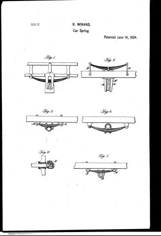
Fig. 1.
Fig. 2.
Fig. 3.
Fig. 4.
Fig. 6.
Fig. 5.
Page 2.
6/14/1834 8261X
June 14, 1834
29.
8261X
June 14, 1834.
The Schedule referred to in these Letters Patent and making part of the same containing a description in the words of the said Prof. Urian himself of his Improvement in the mode of constructing springs to rail road cars
To all whom it may concern. Be it known that I, Prof. Urian of the city of Baltimore in the State of Maryland, Civil Engineer have invented a new and useful improvement in the mode of constructing springs for rail road cars and that the following is a full and exact description thereof, reference being had to the accompanying drawing which make a part of this specification.
The aim perfectly to set forth the nature of my improvement.
First briefly describe the construction of those springs which have been most generally used for rail road cars both in this country and in England. A fig. 1 represents a plate of cast or wrought iron which is bolted into the outside of the side rail of a car and sometimes on both sides of each side rail, a pair of such plates being occasionally used. The parallel sides of these plates serve as guides to the box B, which receives the axle and allows it to follow the motion of the spring and at the same time checks its tendency to lateral or longitudinal deviation. The spring is placed above the box in the manner shown in the drawing, it rests bearing upon plates on the under part of the side rail. These springs are generally made from 30 to 35 inches in length from 2 1/2 to 3 inches deep in the center the plates being from 3 to 3 1/2 inches broad. In Fig. 2, C is a cast or wrought iron frame bolted on to the lower side of the rail of the car, the box of the axle sliding in it as in the former case. The spring C is placed above the car, its ends being attached to links DD, by means of bolts passing through them and through eyes formed in the ends of the springs by screwing in bending them round, or metal bolts to extend from the upper side of the box of the axle to the lower side of the spring. These springs do not differ from the former in their general dimensions. The great expense of springs and construction has induced the promotion of other plans for making them by which it was hoped the interest of cost could be reduced.
Page 3.
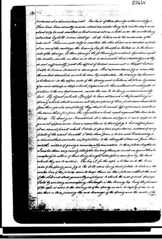
produced at a diminished scale. One kind of these springs is shown at fig 3. These have been usually made about 24 inches long 2 1/4 inches deep and about 2 1/4 broad scrolled or bolted on one or both ends the scrolls being attached by bolts to iron castings &c. &c. bolted on to the underside of the side cast. When one end only is scrolled the other slides in a mortise or hook at in one of the castings, the bearing box for the axle is bolted on to the lower side of the spring. To these springs the following practical objections exist the scroller scrolls on their end tend to diminish their elasticity and they do not sufficiently resist the effect of lateral movement or thrust, but are liable to become loosened or damaged. That represented in fig 4. resembles the one last described as will be seen by inspection. the bearing box however is bolted on to the upper side of the spring and is held in its place by means of an iron strip or strap which passes over it. This without obviating the objections to the one last named, causes the car to be hung in inconveniently low. The object which I profess to have attained is the furnishing a spring which shall answer all the purposes of those first described whilst from their greater simplicity they shall be much less expensive, and be at the same time free from the objections which exist against the two latter kinds. The spring as I construct it is shown at figure 5 and and in its general appearance bears a resemblance to that of fig. 3. but differs from it in several points which I deem of essential importance, instead of using plates of the usual breadth I take them from 4 to 4 1/2 inch broad, using a diminished number in proportion to the strength obtained from their width, instead of giving a considerable curvature to these plates lengthwise I make them very nearly straight, bending them so much only as I think necessary to allow of their being brought straight or nearly so by the load which they are to sustain. The box &c. for the axle is bolted on to the lower side of the spring as in fig 3. the bolts were being well fitted to holes in the centre line of the plates were to keep them in their places without the use of the slots and studs generally employed to check the ends of such springs. I also by avoiding unnecessary thickness in the bearing box being the junction of the axle as near to the lower side of the spring as can be safely done in order that a line joining the two bearings of the spring and the centre of the axle
Page 4.
8261 X
31.
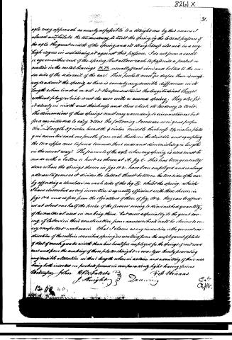
aple may approach as nearly as possible to a straight one, by this means it almost annihilate the tendency to twist the spring by the lateral pressure of the axle. The great width of the spring and its straightness also aid in a very high degree in sustaining it against this pressure. I do not form a socket or eye on either end of the spring, but allow each to pass into a pocket or matric in the metal bearings B B, usually of cast iron, and bolted to the under side of the side rail of the car. These pockets need not be deeper than is necessary to admit the spring, as there is scarcely any sensible difference in its length when loaded or not. It thus prevents the longitudinal thrust without play, which is not the case with a curved spring. They also fit it closely in width and thickness and thus check its tendency to twist. The dimensions of these springs must vary according to circumstances but for a car intended to carry 8 tons the following I consider as in good proportion. Length 37 inches, breadth 4 inches, middle thickness 2 1/4 inches, plates 9 in number, each one fourth of an inch thick in the middle and expanding the two edges ones towards their ends and diminishing in length in the usual way. The journals of the axle when my spring is used must be made with a button or knot as shown at A, fig 6. This has been generally done when the springs shown in figs 1 & 2, have been employed and is always advantageous as it divides the lateral thrust between the two sides of the car by affording a shoulder on each side of the box B, whilst the spring, which I have described as my invention is equally efficient with those shown in figs 1 & 2 and is free from the objections of those of fig. 3 & 4. They can be afforded at about one half the price of the former owing to diminished quantity of the material used in making them, but more especially to the great saving of labour in their construction from causes which will be obvious to every competent workman. What I claim as my invention is the general construction of the within described spring, as resulting from the employment of plates of steel of much greater width than has heretofore employed for the springs of said cars and from the making of those plates straight or near straight thereby preventing any undue alteration in their length when in action, and admitting of their ends being both inserted in pockets formed in comparatively light bearing pieces.
Wm. H. F. F. F. F. F. F. F. F. …
Published accounts: journal notice
Notice in the monthly list of patents, with remarks
Journal of the Franklin Institute, new ser., vol. 15 (1835), p. 36 · View the page
22. For Springs for Rail-road Cars; Ross Winans, Civil Engineer, city of Baltimore, June 14.
Remarks. (See the specification.)
About this record
- Patentee
- DATAMP
- Date
- the Name and Date index of patents, DATAMP, USPTO records
- Invention
- DATAMP
- Listed in
- the Name and Date index of patents, DATAMP, USPTO records, Jim Shaw's X-patent list, the Journal of the Franklin Institute, Burke's List of Patents (1847)
- Burke's 1847 Patent Office list gives the same patent.