

Drawings and documents
National Archives restored drawings: drawing
A. Holbrook and B.F. French's Patent Drawing for a Loom


National Archives, Restored Patent Drawings (Record Group 241) · Full-size scan at the National Archives · Catalog record
Show the text on the drawing Hide (66 words)
Words on the drawing as machine-read by the National Archives; not checked. Useful mainly for searching.
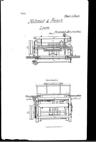
Sheet 1. KG. / X5~LX, / due and B French. / Cruise IDATION / 8266-X / Loom. / Patented. 17. June 1834. / DIVISION. / Plan / Sidc Elevation / 010 / 10 / 12|072 / 111
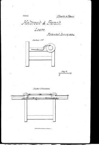
Sheet 2. (69 WEAVING / Looms, Looms / CLASSIFICATION / 8266-X / Section 2ed / DIVISION / to / Fig. 2. / Lathe Elevation / loose need / of / 020
Sheet 3. Loons, Loows / Holbrook from French / June 17, 1834 / End Elevation. / CLASSIFICATION / 8266-X / DIVISION. / Junny / Section. / colo / LOsgood.
USPTO scan
The patent as scanned by the USPTO
-
 Page 1
-
 Page 2
-
 Page 3
-
 Page 4
-
 Page 5
-
 Page 6
-
 Page 7
-
 Page 8
-
 Page 9


U.S. Patent and Trademark Office · Google Patents
Show the transcription Hide (2,511 words)
Machine transcription (LightOnOCR) of the pages as scanned by the USPTO, most of them the handwritten copies made when the records were restored after the 1836 fire. Not checked; it can misread handwriting, so compare it with the scan.
Page 1.
8266X
Sheet 1-3 Sheets.
Holbrook & French.
Loom.
Patented Jun. 17, 1834.
Plan.
Side Elevation.
Page 2.
8266X
Sheet 2-3 Sheets.
Holbrook & French.
Loom.
Patented Jan. 17, 1834.
Section 2nd
Fig. 2.
Lathe Elevation
Page 3.
8266X
Sheet 3-3 Sheets.
Holbrook & French.
Loom.
Patented Jun. 17, 1834.
End Elevation.
Section.
A. PETERS, PHOTO-LITHOGRAPHER, WASHINGTON, D. C.
Page 4.
8266 X
June 17, 1834
Nain Holbrook & Benjamin H. French
Letters Patent
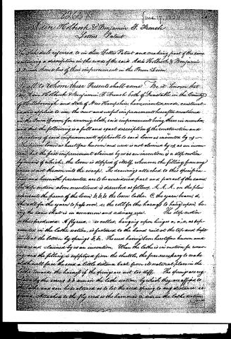
The schedule referred to in these Letters Patent and making part of the same containing a description in the words of the said Nain Holbrook & Benjamin H. French themselves of their improvement in the Power Loom.
To all to Whom these Presents shall come. Be it known that we, Nain Holbrook & Benjamin H. French both of Dunstable in the County of Hillsborough and State of New Hampshire, have invented, made, constructed and applied to use, the new and useful improvement hereafter mentioned in the Power Loom, for weaving cloth, said improvements being three in number, and that the following is a full and exact description of the construction and operation of said improvements applicable to said loom as invented by us.
The power loom as heretofore known and used is not claimed by us as an invention, but the first improvement claimed by us as an invention, is a stop motion by means of which, the loom is stopped of itself, whenever the filling (from any cause) is not thrown into the warp. The drawings attached to this specification and herewith presented are to be considered part and parcel of the same.
The stop motion above mentioned is described as follows. A. A. A. on the plan represents the frame of the loom; b, b, b, the loom lattice. C, the yarn beam; d, the roll for the yarn to pass over; e, the roll for the harniss to hang upon, being the same that is in common and ordinary use.
The stop motion is thus produced. A flywheel, so called, hanging upon hinges a, a, a, as represented in the lattice section, is fastened to the hand rail at the top and kept in its place at the bottom by springs b, b. This wheel having been heretofore known and used is not claimed by us as an invention. When the lattice is in motion for weaving, and the filling is supplied from the shuttle, the force necessary to make cloth will force the wheel a little distance back from its natural place in the lattice towards the harniss if the springs are not too stiff. The springs are regulated by the screws b, b, seen in the lattice section, by which they are affixed to the lattice and can here altered as to let the wheel spring to any distance as required. Attached to the flywheel is the hammer c, seen in the lattice section.
Page 5.
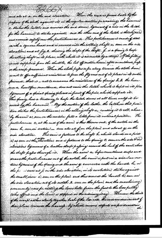
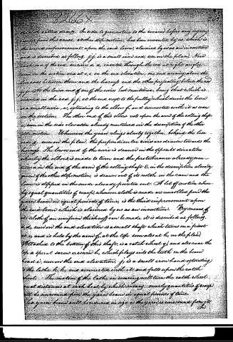
and also at a, on the end elevation. When the reed is freed back by the pressure of the cloth against it, in the regular motion for weaving, the hammer c, strikes the latch and crowds the end down, by means of a rise in the latch, for the hammer to strike against, and the other end of the latch is thereby raised and carried safely over the protuberance d. This protuberance is made of steel, with a square head, and is screwed into the rolling shaft e, seen on the side elevation, and at fig. 2, showing the shape of the shaft. f, is a spring to keep the rolling shaft in its place, with which it is connected by a strap. If the filling is not supplied from the shuttle, the let off motion herein often mentioned, helps the warp forward. When the cloth passes so far along towards the cloth beam, as not to offer sufficient resistance to force the fly reed out of its place in its motion forward—that is—not to overcome the resistance of the springs B, B, the hammer a, heretofore mentioned, does not raise the latch which is kept in its place by means of a special spring placed in front of the pivot, which supports it. This spring has a tendency to keep the latch down at all times, unless it be raised by the hammer. By the motion of the latch, the latch, in this position, strikes the protuberance, in the rolling shaft e, causing it to roll, where—by the arm a, seen on the section, falls a little from its natural position. The protuberance c, at the end of the arm, is thus thrown out, of the notch in the cam h, seen in section—seen also at f, on the plan, and also at g, on the side elevation. This cam is fastened to the shaft h, which stands on a pivot i, as seen on the side elevation, and is fastened to the spring C, seen on the side and elevations by means of a leather strap passing around the hub of the cam, where the shaft passes through it. When the arm a, before mentioned rises and draws the protuberance out of the notch, the cam is put in a circular motion by means of the spring and the arm g, connected with the handle k, on the fig. 1 seen at j, on the side elevation, in its revolution, strikes against the small pin i, seen on the plan, and thus crowds the handle k, seen on the side elevation out of its notch, b, seen on the plan, and the machinery commonly used for cutting the loom belts, from the fast to the loose pulley, takes effect and the loom is stopped in the ordinary way. Whenever the thread of the warp adheres closely together, back of the loom ends, there are drawn out of their place towards the hangers, by which means, defects are produced in the
Page 6.
the cloth called draw, in order to give notice to the weaver before any injury results from this cause, another improvement has been invented by us, which is the second improvement upon the said loom, claimed by us as an invention and is described as follows. j, j, is a small iron rod, seen on the plan. Near each end of the rod, screws a, a, inserted through the rod at right angles, seen on the section one at o, o, on the end elevation, one end arising above the line and between them and the harness and the other projecting below the rod j, j. At the lower end of one of the wires last mentioned, being that which is inserted in the rod j, j, at the end next to the pulley which drives the loom is a small wire e, extending to the elbow f, and connected with it as seen on the section. The other end of this elbow rests upon the arm of the rolling shaft e, seen in the side elevation already mentioned in the description of the other improvement. Whenever the yarns cling closely together, behind the case end g, seen on the plan, the perpendicular wires are drawn towards the harness. The lower end of the wire is drawn in the opposite direction whereby the elbow is made to turn and the first tubercle already mentioned in the end of the arm of the rolling shaft e, in the description already given of the other improvement, is drawn out of its notch in the case and the loom is stopped in the mode already pointed out. A let off motion whereby equal quantities of warp, whenever cloth is made are unwound from the yarn beam in equal periods of time, is the third improvement upon the said loom which is claimed by us as an invention. By means of it cloth of an uniform thickness can be made it is described as follows. k, k, seen on the end elevation is a small shaft which turns on a pivot at e, and is held by the arm f, at the top, seen also at k, on the plan. Attached to the bottom of this shaft, is a ratchet wheel g, and also near the top a spiral screw or worm h, which plays into the teeth on the beam head i, seen on the end elevation. j, is a small iron hand extending to the lathe k, k, and connected with it, and falls upon the ratchet wheel. The motion of the lathe in weaving will turn the ratchet wheel equal distances at each beat, by which means, nearly quantities of warp will be unwound from the yarn beam in equal periods of time. The yarn beam will therefore in size as the yarn is unwound from it.
Page 7.
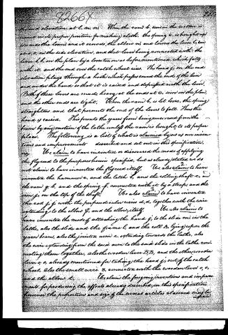
In order then to have equal quantities of warp let off in equal times, it will be necessary to turn the beater head farther and farther as the yarn beam becomes gradually smaller. It will therefore be necessary to turn the catch wheel farther in proportion, as the yarn beam becomes smaller. This is accomplished thus, l, seen on the plan, is a piece of wood with two pieces of iron m, m, screwed to it tight, so as to form a stiff frame. The frame rests upon an arm o, o, fastened into the stand p, a, is a small iron roll that acts upon the yarn beam as rises or lowers the frame, as the yarn beam varies in size. This frame as seen at h, on section 2nd showing the shape of the irons and the position it lies in. At the bottom of this frame is an arm b, extending to the lathe. This arm b is in two pieces, but connected by a loose joint at o, on the pin is that the frame containing the roll may be turned up towards the harness far enough to put in and take out beams. The arm b, thus connected extends to the lathe. From the end of the arm next the lathe, is a small wire l, seen on the side elevation extending down the lathe and connected with the slide m, which slides in grooves made in two pieces of wood and fastened to the lathe seen on the side elevation at o, o. The end of the hand j seen on the end elevation is fastened into the slide m, seen on the side elevation, and when the frame l, seen on the plan is lowered, the arm j seen on the section is raised and that being connected with the slide as before mentioned, the slide is raised and the end of the hand j, with it. By this means the hand is pushed farther, and the catch wheel is turned farther and this being connected with the beam as already mentioned, the beam will turn farther, and it will turn off equal quantities of warp in equal times, when the filling is up, tied from the bobbin. When the filling is not supplied, and the loom in consequence stops, the hand j, is taken off from the catch wheel in the following manner. B, B, on the plan represents a lever of wood running across over of the loom from the catch wheel to the lathe, having its middle upon a pin or stay a. It is fastened to another lever of wood o, o, seen on the side elevation, by a loose tenon, so that it cannot bind at the corner of the loom marked c, in the plan. At the end o, seen on the side elevation is a small wire s, extending to the elbow b, seen also on the
Page 8.
side and elevation, at l, m, m. When the cam b, seen in the section is turned in its proper position for making cloth, the spring e, is brought up towards the loom, and it causes the elbow m, and lowers the lever l, seen at o, o, on the side elevations, and that lever being connected with the lever l, b, on the plan by a loose tenon as before mentioned, which falls with it, and the end over the ratchet wheel rises. The hand j, on the end elevation plays through a hook which passes round the end of the lever and under the hand so that it is raised and deprived with the lever. Both of these levers are made heavy at the ends at e, seen on the plan, and the other ends are light. When the cam b, is let loose, the spring straightens, and that permits the end of the levers to fall. Thus the hand is raised. This prevents the yarn from being unwound from the beam by any motion of the loom unless the cam is brought to its proper place. The following is a list of what is claimed by us as our inventions and improvements described and set out in this specification.
We claim to have invented or discovered the mode of applying the flyreed to the purposes herein specified, but as already stated we do not claim to have invented the flyreed itself. We also claim to have invented the hammer e, and the latch b, and the rolling shaft e, and the cam g, b, and the spring f, connected with it by a strap, and the iron j, on the top of the shaft. We also claim to have invented the rod j, j, with the perpendicular wires d, d, together with the wire extending to the elbow f, and the elbow itself. We also claim to have invented the mode of attaching the hand j, to the slide m, in the loom, also the slide and the frame l, and the roll A, lying upon the yarn beam, also the jointed arm e, extending towards the loom, also the wire extending from the said arm to the said slide in the loom connecting them together, also the wooden lever B, B, and the other wooden lever o, o, already mentioned for taking the hand j, out of the ratchet wheel, also the small wire B, connected with the wooden lever o, o, and the elbow t.
We claim the foregoing inventions and improvements for producing the effects already described on this specification. However the proportions and size of the several articles claimed may be
Page 9.
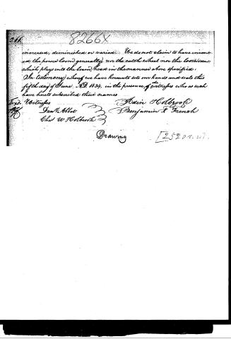
increased, diminished or varied. We do not claim to have invented the power loom generally, nor the catch wheel nor the loom screw which plays into the beam, head in the manner above specified.
In testimony whereof we have hereunto set our hands and seals this fifth day of June A.D. 1834, in the presence of witnesses who as such have hereto subscribed their names.
Wid. Witnesses
Jan H. Abbot
Wm W. Holbrook
Hain Holbrook
Benjamin A. Green
Drawing
[25201.01]
Published accounts: journal notice
Notice in the monthly list of patents, with remarks
Journal of the Franklin Institute, new ser., vol. 15 (1835), p. 41 · View the page
36. For improvements in the Power Loom; Aden Holbrook, and Benjamin F. French, Dunstable, Hillsborough county, New Hampshire, June 17.
Remarks. The specification of this patent refers throughout to the accompanying drawings, which are very perfect, and are necessary to a complete understanding of the things claimed. The improvements made are three in number; the first "is a stop motion, by means of which the loom is stopped of itself, whenever the filling, from any cause, is not thrown into the warp." "Whenever the threads of the warp adhere closely together back of the lese rods, the rods are drawn out of their place towards the harness, by which means defects are produced in the cloth, called draws. In order to give notice to the weaver before any injury arises from this cause, another stop motion has been invented by us, which is the second improvement upon the said loom claimed by us as our invention." "A let off motion, whereby equal quantities of warp, whenever cloth is made, are unrolled from the yarn beam in equal periods of time, is the third improvement upon the said loom which is claimed by us as our invention. By means of it, cloth of an uniform thickness can be made; it is described as follows," &c. We have thus indicated, in the words of the patentees, the object of their improvements, which is all that we can now do.
About this record
- Patentee
- DATAMP
- Date
- the Name and Date index of patents, DATAMP, USPTO records
- Invention
- DATAMP
- Listed in
- the Name and Date index of patents, DATAMP, USPTO records, Jim Shaw's X-patent list, the Journal of the Franklin Institute, Burke's List of Patents (1847)
- Burke's 1847 Patent Office list gives the same patent.