

Drawings and documents
National Archives restored drawings: drawing
H. Strait's Patent Drawing for a Balancing Valves


National Archives, Restored Patent Drawings (Record Group 241) · Full-size scan at the National Archives · Catalog record
Show the text on the drawing Hide (80 words)
Words on the drawing as machine-read by the National Archives; not checked. Useful mainly for searching.
Sheet 1. slide Values St Eug- / me 19. page 429 / 500 / 136. VALVES. / [152] Balanced. / CLASSIFICATION / 8283-X / LIVISION. / Ho I trails / Balance Valves. / Patented 25 June 7834 / OIR / Fight Pis 2. Pig'3 Fig4 I'ig or / Percussion / Wings / Bellows / Airpump / Water pump / Air of / Water / paims / 22 / WT / is / 11 / M f effries Y of bellows I' 2 or pump
Sheet 2. 104 H.Strait, / 8283X / Steam Balanced Valre. / Patented June 25,1834. / 2 Figh rig.3 Figh Fig.5 / II. / Fig.1 / in
USPTO scan
The patent as scanned by the USPTO
-
 Page 1
-
 Page 2
-
 Page 3
-
 Page 4


U.S. Patent and Trademark Office · Google Patents
Show the transcription Hide (1,549 words)
Machine transcription (LightOnOCR) of the pages as scanned by the USPTO, most of them the handwritten copies made when the records were restored after the 1836 fire. Not checked; it can misread handwriting, so compare it with the scan.
Page 1.
8283X
H. Strait,
Steam Balanced Valve.
Patented June 26, 1834
Fig. 1
Fig. 2
Fig. 3
Fig. 4
Fig. 5
<table>
<tr>
<td>α</td>
…
Page 2.
June 25, 1834
William Street of East Rutherford, New York
Letters Patent
The Schedule referred to in these Letters Patent and making part of the same, containing a description in the words of the said William Street himself of his improvement in the construction and application of valves on the principle of a Balance.
To all to whom these presents shall come: We it known that William Street of East Rutherford, in the County of Rensselaer and State of New York, have invented a new and useful improvement in the construction, application and operation of valves, on the principle of a Balance, for the purpose of pressurizing, compressing and exhausting air and water, and that the following is a full and exact description of the construction, application and operation of valves on the said principle of a Balance as invented by me.
A represents the model to illustrate the construction, application and operation of valves on the principle of a Balance, to create a powerful percussion on air, or, or, or, represents its sides, which are four, of equal length and strongly joined together at their corners. a, a, represents its balancing centre or axle, which is strongly connected to the middle of the sides, or, or. Then small horizontal lines drawn from a to m, parallel to the axle, a, a, represent small wires broken through their sides. b, b, represent a thin narrow stiff slip of light cloth paper or metal a little wider than to fill one interval between those wires, and as long as m, or, c. This slip b, b, is to be nearly balanced & moveably hung across the wire, w, w. The heaviest side or sides is to hang down and be restrained so as to open at any angle by means of the strings c, c, which are attached to the side, m. Slips are to be similarly hung on all the small parallel wires and restrained by strings c, c, c, c. When this is done, the handle H, which is the common handle, to operate the different modifications of the same principle in the model is to be moved quickly up and down which will cause a constant and powerful percussion on the air, and consequently reaction which will either propel or elevate as it is hung horizontally or perpendicularly. The slips may likewise be hung by one of their long sides and not balanced, though similarly restrained. When the handle H is raised all the valves between m, and a, a, close air tight and strike the air, while those between c, and a, a, open and let the incoming air through; when brought down, those that closed, open and those that opened close, so that it will strike the same one way as the other. The edge weight and shape of the wings to create percussion hung on this principle of a balance are variable, but the principle of operation the same. The use for which I claim this valuable illustration of the
Page 3.
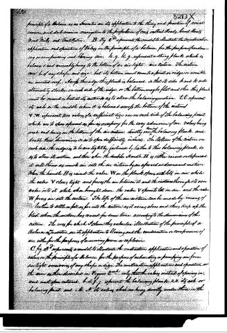
principle of a Balance as an indicator, and its application to the theory and practice of aerial marine, and sub-marine navigation to the propulsion of cars, railroads, canal boats, Wind Mills, and Ventilators. B Fig 2 represents this model to illustrate the construction, application, and operation of Valves on the principle of a balance, for the purpose of condensing or compressing and blowing air. H, y, H, g, represent a strong plank which is balanced and movable by hanging to the bottom of an air tight air cistern. The cistern can be of any shape and size, but its bottom must come to a point or ridge resembling an inverted roof. Across this ridge this plank is balanced, so that its sides h and k will alternately strike on each side of the ridge, or the bottom may be flat and then this plank must be curved so that at its center it allows the balancing motion. t, t, represent its axle in the middle when it is balanced across the bottom of the cistern. V, W, represent two valves of a sufficient size, one on each side of the balancing point which are to show opened as far as necessary for the easy admission of air. Valves being made and hung on the bottom of the air cistern, directly over the balancing plank, and double their diameters, so as to open sufficiently inwardly. The bottom of the cistern on each side the ridge is to be air tight by fastening by leather to this balancing plank, so as to allow its motion, and then when the double Handle H is either raised or depressed it will throw as much air into the air cistern by an upward or downward motion. When the handle H is raised the valve W in the plank opens and lets in air, while the valve V closes tight and forces the air between it and the cistern through its own valve into it, while when brought down, the valve V opens to let in air, and the valve W forces air into the cistern. The top of the air cistern can be made by means of leather to settle or fall as far into the cistern as it rises above and thus keep up the blast when the motion has ceased for some time, according to the diameters of the cistern. The uses for which I claim this subaerial illustration of the principle of a Balance as an indicator, and its application to blowing and the condensation or compression of air, either for the purposes of a moving force or explosion. C Fig 3 represents a model to illustrate the construction, application, and operation of valves on the principle of a Balance, for the purpose of exhausting or pumping air from an air tight reservoir of any shape or size. The construction, application, and operation are the same as those described on Figure 2, only that the valves instead of opening inward must open outward. b, d, f, g, represent the balancing plank, 2, 2, its axle or balancing point, and e, h, N, its valves which are hung directly under those in the
Page 4.
bottom of the reservoir to be exhausted of air. The uses for which I claim this valvular illustration of the principle of a Balance as an Inventor are its application to the exhausting of air from all kinds of Reservoirs within for practical or scientific purposes.
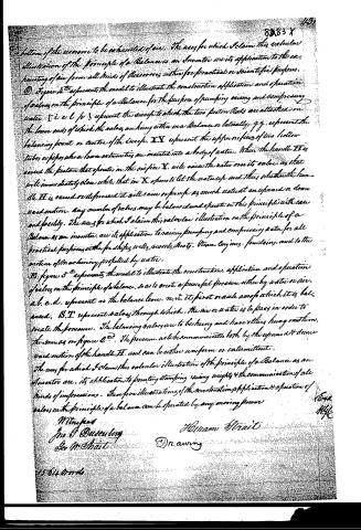
D. Figure 2nd represents the model to illustrate the construction, application and operation of valves on the principle of a Balance for the purpose of pumping, raising and compressing water. E i.e. l p 3 represent the sweep to which the two piston Rods are attached on the lower ends of which the valves are hung either on a Balance or laterally, g.g. represent the balancing point or center of the sweep. XX represent the upper orifices of two hollow tubes or pipes whose lower extremities are inserted into a body of water. When the handle H is raised the piston that operates in the orifice X will raise the water over its valve, as that will immediately close while that in X opens to let the water up and thus whether the handle H is raised or depressed it will raise or pump as much water at an upward or downward motion. Any number of tubes may be balanced and operate on this principle with ease and facility. The uses for which I claim this valvular illustration on the principle of a Balance as an Inventor are its application to raising, pumping and compressing water for all practical purposes either for deep wells, reservoirs, boats, Steam Engines, fountains, and to the action of machinery propelled by water.
E. Figure 3rd represents the model to illustrate the construction, application and operation of valves on the principle of a Balance, so as to create a powerful pressure either by water or air. a.b.c.d. represent as the balance lever, m.n. its pivot or axle upon which it is balanced. S.T. represent valves through which the air or water is to pass in order to create the pressure. The balancing valves are to be hung and have others hung on them. The same as in figure 2nd. The pressure will be communicated both by the upward & downward motion of the handle H. and can be either uniform or intermittent.
The uses for which I claim this valvular illustration of the principle of a Balance as an Inventor are, its application to printing, stamping, raising weights & the communication of all kinds of impressions. These are illustrations of the construction, application & operation of valves on the principle of a balance can be operated by any moving power.
Witnesses
Jno G. Dusenbury
Geo M. Strait
Hiram Strait
Drawing
15th April 1866
8883 X
149)
Ford
M.H.C.
Published accounts: journal notice
Notice in the monthly list of patents, with remarks
Journal of the Franklin Institute, new ser., vol. 15 (1835), p. 46 · View the page
51. For Lever Valves for exhausting Air and Water; Hiram Strait, East Nassau, Rensselaer county, New York, June 25.
Remarks. We are informed that the improvement here patented consists in the "application and operation of valves, on the principle of a balance, for the purpose of percussing, compressing, and exhausting, air and water;" and this information is followed by an intended exemplification of the different modes in which this principle of a balance valve is to be applied. The whole affair, however, is a "fancy's sketch," which never will, because it never can, be brought into practical operation, so as to produce any useful effect, in either of its forms. The principle alluded to is the placing a rod or shaft so as to turn, or rather vibrate, on gudgeons, and attaching to it two somethings, that the patentee calls valves, which are opposite to, and balance, each other. In the plan first described, which is to operate upon air, the valves on each side of the rod are to consist of narrow, parallel curtains, standing somewhat in the manner of the slats of blinds, which are alternately to open and close by vibrating the apparatus; and this is to be applied "to the theory and practice of aerial, marine, and submarine navigation: to the propulsion of cars on railroads, boats, windmills, and ventilation;" how, we do not learn, and never shall. With this item of the information communicated, we dismiss the subject, lest we should not do it adequate justice.
About this record
- Patentee
- DATAMP
- Date
- the Name and Date index of patents, DATAMP, USPTO records
- Invention
- DATAMP
- Listed in
- the Name and Date index of patents, DATAMP, USPTO records, Jim Shaw's X-patent list, the Journal of the Franklin Institute, Burke's List of Patents (1847)
- Burke's 1847 Patent Office list gives the same patent.