

Drawings and documents
National Archives restored drawings: drawing
R.C. and C.O. Read's Patent Drawing for a Wood Screw Machine


National Archives, Restored Patent Drawings (Record Group 241) · Full-size scan at the National Archives · Catalog record
Show the text on the drawing Hide (90 words)
Words on the drawing as machine-read by the National Archives; not checked. Useful mainly for searching.
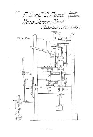
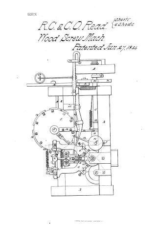
Sheet 1. №10. / R.C. & C.O. READ'S / CLASSIFICATION / 8287-+ / WOOD SCREW MACHINE. / 1834 / DIVISION / PLATE 1. FRONT VIEW / 10. / 10 / 0. / 43 / raf / 40 / 16 / 19 / 44 / 17 / 45 / 36 / 35 / 37 / 28 / 28 / 42 / M. / I, / 24 / 3/0 / For / 23 / 30
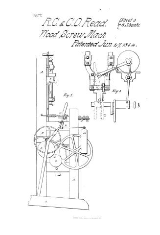
Sheet 2. CLASSIFICATION / 8287-X / DIVISION. / PLATE 3. END VIEW. / 10 / E' / Fig.3. / Cry / 2. / Fig.1. / 12 / 18 / II / 25 / COL / 45 / 40 / 20 / C, / 29 / 27 / 42 / 31 / 30
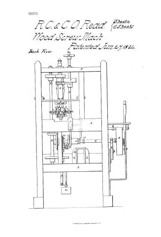
Sheet 3. CLASSIFICATION / PLATE 2 BACK view. / 8287-X DIVISION. / 10 / 40 / Du / 26 / 11 / 39 / 27 / 42 / If
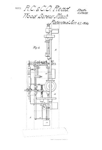
Sheet 4. 10. METAL WORKING / Wood Screw Machines. / Plate / 66 Sheets3 Sheet / 15 / R.C.&CO. Read / CLASSI TICATION / Wood Screw Machine / 82 8287-X X / DIVISION. / Patented June 27th1834> 1834 / 10 / Front View / 43 / .2 / 40 / 76 / 16 / 18 / 44 / 17 / 45 / 36 / 35 / 337 / 29 / 42 / 24 / 31 / is / Fig.2 / 12 / 23 / 30
USPTO scan
The patent as scanned by the USPTO
-
 Page 1
-
 Page 2
-
 Page 3
-
 Page 4
-
 Page 5
-
 Page 6
-
 Page 7
-
 Page 8
-
 Page 9


U.S. Patent and Trademark Office · Google Patents
Show the transcription Hide (2,642 words)
Machine transcription (LightOnOCR) of the pages as scanned by the USPTO, most of them the handwritten copies made when the records were restored after the 1836 fire. Not checked; it can misread handwriting, so compare it with the scan.
Page 1.
8287X
R.C. & C.O. Read. $\left\{ \begin{array}{l} \text{Sheet 1} \\ \text{6 Sheets} \end{array} \right.$
Wood Screw Mach.
Patented Jun. 27, 1834.
Front View.
Fig. 2.
N. PETERS, PHOTO LITHOGRAPHER, WASHINGTON D.C.
Page 2.
8287X
R.C. & C.O. Read. $\left\{ \begin{array}{l} \text{Sheet 2} \\ \text{6 Sheets} \end{array} \right.$
Wood Screw Mach.
Patented Jun. 27, 1834
Back View.

W. PETERS, PHOTO-LITHOGRAPHER, WASHINGTON D.C.
Page 3.
8287X
R.C. & C.O. Read.
Wood Screw Mach.
Patented Jun. 27, 1834.
Sheet 3
6 Sheets.
Fig. 1.
Fig. 3.
Page 4.
8287X
R.C. & C.O. Read.
Wood Screw Mach.
Patented Jun. 27, 1884
Sheet 4
6 Sheets.
Fig. 2.
A.
C.
H.
A.
A.
30
Y. PETERS, PHOTO-LITHOGRAPHER, WASHINGTON, D.C.
Page 5.
8287X
R.C. & C.O. Read. $\left\{ \begin{array}{l} \text{5 sheets} \\ \text{6 sheets} \end{array} \right.$
Wood Screw Mach.
Patented Jun. 27, 1834

Page 6.
8287X
R.C. & C.O. Read. $\left\{ \begin{array}{l} \text{Sheet 6} \\ \text{6 Sheets} \end{array} \right.$
Wood Screw Mach.
Patented Jun. 27, 1834.
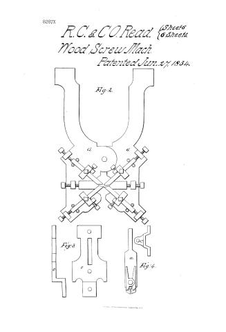
Fig. 2.
Fig. 3.
Fig. 4.
I. E. ELLIS, PATENT LITHOGRAPHER, WASHINGTON, D.C.
Page 7.
8287X
UNITED STATES PATENT OFFICE.
RUFUS C. READ AND CLEMENT O. READ, OF WORCESTER, MASSACHUSETTS.
MACHINE FOR MANUFACTURING WOOD-SCREWS.
Specification forming part of Letters Patent dated June 27, 1884.
To all whom it may concern:
Be it known that we, RUFUS C. READ and CLEMENT O. READ, of the town of Worcester, in the county of Worcester and State of Massachusetts, have invented a new and useful Improvement in Machines for Manufacturing Wood-Screws; and we do hereby declare that the following is a full and exact description thereof, reference being had to the drawings which accompany and make a part of this specification.
The improvement made by us is in that of the machinery which is used for cutting the worm or thread, the preparation of the blank on the cutting of the wire, heading, and nicking being effected by any of the machines used for that purpose.
In our machine for cutting the thread the shaft which is to receive and carry the blank is made to revolve vertically, the nippers which clasp and hold it being at the lower end thereof, so that when they are opened the screw is in the best position to fall therefrom by its own gravity. From the manner in which we construct and give motion to this shaft it is kept in continual motion, the feeding being effected without the necessity of stopping it and in such a way that one individual can tend and feed a number of machines.
The frame A A A A, which supports the machine, is an oblong square, the back part rising above the front, (see plates,) the cross-pieces at the bottom being sufficiently long to keep the machine steady.
We shall describe first the manner in which motion is communicated to the vertical shaft E, which holds the screw. Power is applied to the pulley B on the horizontal shaft C, which communicates motion to the vertical shaft D by a pair of bevel-wheels, and this shaft, by a pair of spur-wheels, gives the required motion to the shaft E.
Second. The manner in which the screw is held. A pair of nippers (marked 1) are inserted in the lower end of this shaft, in which are inserted a pair of steel dies 2, with grooves cut to correspond with the head of the screw, and so made that the screw will revolve perfectly true with the shaft. A ring 3 is placed on the shaft around the nippers, in order to form a proper bearing for the lower end of the shaft to revolve in the box 4. To open and shut the nippers, a sliding collar 5 is fitted on this shaft to act on the handle of the nippers. The nippers are opened by a spring on the momentum of a shaft. To move the collar 5 up and down, a clutch 6 is inserted in a groove in the collar 5. Through this clutch is passed a vertical rod F, made to slide in the fastenings 7 and 8. A weight 9 is placed on the clutch. In order to shut the nippers with sufficient strength, 10 is a place where additional weight may be placed, when necessary. The weight and rod are raised by a cam 11 on the shaft C acting against a roll in the lower end of the sliding rod F, which is kept up the proper time by a latch 12 catching in a notch in the rod, against which it is held by a spring. (Not shown in the drawings. See Plate 1, Fig. 2.)
Third. The manner in which the chisels are applied to cut the thread. There are four tools used—two as chisels and two as rests 13 13 13 13. They are placed diagonally with the frame on two plates of iron, which we call “jaws” G G. The chisels are held firm by staples 14, through which they pass, and screws 15, by which the points of the chisels may be moved in any direction required. (See Plate 4, Fig. 2.) The jaws G G are fitted together by a joint near the center to open and shut. Power to act on these jaws and bring the chisels to act on the screw is applied at the opposite end. They are opened by means of a spring 20 by a vertical vibrating shaft H, which we call a “fan-shaft.” This has two broad plates—one at the top and another near the bottom, across the center. When the jaws are opened, they stand in an angular position. As it is moved round square with the jaws it gradually shuts them by pressing against inclined planes 16 16, screwed on the ends or handles of the jaws. This shaft is also brought back by a spring 17, but prevented from turning too far by a pin projecting out of the shaft striking the frame. To vibrate this shaft there is a large horizontal plate I, firmly fastened to the top of the shaft J. On the under side of this shaft are bolted five segments 18 18 18 18 18, the edges of which project a little beyond the plate. As the plate revolves, these plates or segments act against an arm 19, inserted in the fore shaft H. The number of these segments is optional, as the
Page 8.
number gives the number of times the chisels will act on the screw. The shaft J is an important part of the machine, as all the motions except the revolving ones proceed from it either directly or indirectly. Motion is communicated to this shaft by a pinion 20 on the main shaft C. This gears into a stud-wheel K, which connects with the stud-wheel L. The last-named stud-wheels are screwed together with nuts on a hollow arbor, that they may be changed, if necessary, as on the comparative size of these wheels the velocity of the shaft J, and consequently the space traversed by the jaws, depend, as will be hereinafter shown. These wheels connect with a large wheel M on the horizontal shaft N, which by a pair of bevel-wheels gives the required motion to the shaft J.
Fourth. Having described the manner in which the chisels are brought to act on the screw, it is necessary that the shaft E on the jaws G should recede as the screw turns. This motion is given to the jaws; but we should first describe how they are attached. The jaws G are made fast to an iron plate o by a double shoulder-bolt, so as to form a close joint. The plate o is screwed to the top of a pair of rods P P, which are connected by a cross-piece 23 at the bottom and forms a kind of frame which we call "sliding frame." The bars pass through a cross-bar 24 near the bottom and a piece of iron 25 near the top on the outside of each, with grooves. Through these they slide freely in a perpendicular direction. Between these rods, near the center, is another plate R, which is fastened to the rods. Through the center of this plate is a hole about one and one-fourth inch diameter. Through this hole is passed a vertical revolving shaft of about one inch diameter, on the upper part of which is a screw of the same fineness of thread as intended for the screw to be cut. This we call "leading-screw" S. The bottom of this screw is inserted in a step in the bar 26, passing across the frame of the machine. The leading-screw is separate from the sliding frame and does not touch it. Motion is given this screw by a wheel on the lower part of it connecting with a similar one on the shaft D, by which the leading-screw is propelled by a constant rotary motion.
Fifth. To give the required perpendicular motion to the jaws and sliding frame a pair of dies 27 27, of a corresponding thread with the leading-screw, are placed upon the plate R on opposite sides of the leading-screw. To each of these dies is attached the end of a lever 28 28. These levers near their center are bolted to the plate R, so as to form their fulcrum. The opposite ends extend to the lower end of the fan-shaft H. Pieces of steel 29 29 are fastened on the opposite ends of these levers, against which the fan-shaft H acts, by a flat plate similar to that which acts on the jaws. (For a view of this part of the machine see Plate 3, Fig. 3.) It will be seen that turning the fan-shaft so as to bring it nearly square with the levers 28 28 the leading-dies 27 27 are pressed firmly against the screw S, which, revolving in the proper direction, will move them and consequently the plate R. The jaws G G and the whole sliding frame regularly down, they are brought up by the weight 30, attached to the sliding frame by a cord passing over a sheave 30 and fastened to the cross-piece 23. The sliding frame is prevented from rising too far by a collar screwed on one of the rods P striking the cross-bar 24.
We shall next describe the manner of carrying the blank into the nippers. Upon the plate o and partly over the jaws is a small sliding plate a, sliding in grooves in one end, formed in a part of the bolt which holds the jaws b b, and the other end through a hole in a stand o on this side is placed a pair of fingers d d, matched together by a joint. The blank is placed between the fingers at c, against which they are pressed by a spring f. A stem g projects below the slide a, which is taken hold of by the lever T.
Having described the principal parts of the machine, we now proceed to show the process by which a screw is cut.
The drawings represent the machine in the situation in which it appears when the screw is completed and is dropping from the nippers. The blank is placed between the fingers at c during the operation of cutting the last screw. The first movement is the inclined plane 34 on the plate I as it revolves presses against the roll in the horizontal lever T, which moves the slide and the blank set on it under the nippers. While held in this position, the steel segment 18 moves away from the arms 19 in the fan-shaft, which is turned back by the spring 17. The jaws g g and levers 28 being thus set at liberty, they are opened by the spiral springs. (Shown in the drawings.) The sliding frame being thus set free it is raised by the weight 30 far enough for the head of the blank to be just even with the groove in the dies 22 in the nippers 11, when an arm 35, screwed on the sliding frame, is caught by another arm 31, screwed to the projecting shaft J. At the moment a piece of iron bolted on the plate I moves the end of the latch 12 away from the notch in the sliding rod F and the weight is dropped, the sliding collar 5 brought down, and the blank thus caught between the dies. The piece 34 then moves away, and by means of a spring on the end lever T the slide a and fingers d d are brought back. Then the arm 36 moves away from the arm 35 and the sliding frame vised till stopped by the collar 32. The machine is then ready to commence cutting the screw, which is done by the next segment 18 pressing against the arm 19, which turns the fan-shaft, and this acting against the steel pieces 29 29 on the levers 28 28 the leading-dies 27 are brought firmly against the leading-screw S. As soon as the sliding frame begins to move, the chisels are brought to act on the blank. The sliding frame moves
Page 9.
gradually down till the first segment 18 has moved away from the arm 19, when the fan-shaft flies back, as before described, and the sliding frame again rises to the stop 32. Then the next segment comes to act in a similar manner. This and every succeeding segment is projected a little farther out from the plate, and thus turns the fan-shaft a little farther and consequently brings the chisels deeper in the screw. This is repeated till the last or fifth segment has brought the chisel below the screw. This segment is longer than the others in order to bring the blank sufficiently low to pass under the nippers. When the arm 37 passes against the end of the lever or fork 38, which moves the cam 11 under the sliding rod F, (see Plate 3, Fig. 3,) when a catch in the cam is caught by an arm on the shaft C, which causes it to revolve and the screw drops. The rod 44 (partially seen in Plates 1, 2, and 4) is designed as a guard against injury to the chisels. Should the blank, by being too small or from any other cause, not be held sufficiently firm by the dies 22 to overcome the resistance of the chisels, the bar 26, which holds the top of the leading-screw, is fastened only at one end, the other held upon the screw by the weight 45 by means of arms attached to the rod 44. Should the blank not turn, the resistance of the chisels to the descent of the sliding frame would overcome the resistance of the weight 45, the leading-screw would rise, and by an arm in the rod 44, lying against the belt-handle 40, it would be moved from the catch that holds it and the machine would stop till readjusted. This apparatus is never needed when the machine is in order and properly attended. Most of the operative parts of the machine as within described are such as are well known and are used in other machines, but differently combined together. We do not therefore claim them in their individual characters as making any part of our invention; but
What we do claim is—
1. Placing the main shaft which carries the same vertically and the giving to it a continuous motion by the general arrangement of the parts described.
2. The mode of feeding herein set forth as adapted to the motion of the vertical shaft; and we do hereby declare that while we claim the general principles or mode of action of the vertical shaft and its appendages, we do not intend to confine ourselves to the exact mode of construction herein set forth, but to vary the same in any manner which we may deem proper, while the principle of action remains the same and similar results are obtained.
RUFUS C. READ.
CLEMENT O. READ.
Witnesses:
ABEL HOWE,
EMORY WASHBURN.
Published accounts: journal notice
Notice in the monthly list of patents
Journal of the Franklin Institute, new ser., vol. 15 (1835), p. 48 · View the page
56. For improvements in the Machinery for Manufacturing Wood Screws; Rufus C. and Clement O. Reed, Worcester, Worcester county, Massachusetts, June 28.
About this record
- Patentee
- DATAMP
- Date
- the Name and Date index of patents, DATAMP, USPTO records
- Invention
- DATAMP
- Listed in
- the Name and Date index of patents, DATAMP, USPTO records, Jim Shaw's X-patent list, the Journal of the Franklin Institute, Burke's List of Patents (1847)
- The Franklin Institute's journal gives a different date.
- Burke's 1847 Patent Office list gives the same patent.