

Drawings and documents
National Archives restored drawings: drawing
Samuel P. Mason's Patent Drawing for a Machine for Whipping and Cleaning Cotton

National Archives, Restored Patent Drawings (Record Group 241) · Full-size scan at the National Archives · Catalog record
Show the text on the drawing Hide (61 words)
Words on the drawing as machine-read by the National Archives; not checked. Useful mainly for searching.
19. CARDING. - Cotton / [26] Pickers. / SAMUEL P. MASON'S / 1834 / $350 / WHIPPING, AND CLEANING COTTON. / Patented 8th July 183, / ASSIFICATION / 8295-+ DIVISION. / Fig 1. / Fig. 2. / Vol 18% 50% / F. / C. / D. / L. / A. / b. / 1F. / B. / A. / A. / B. / A. / Fig. 3. / I. / IF / 0896 / O. / Fig. 4. / F. / M. / E. / HY / E. / 0.00000 / HO / GB
USPTO scan
The patent as scanned by the USPTO
-
 Page 1
-
 Page 2
-
 Page 3
-
 Page 4


U.S. Patent and Trademark Office · Google Patents
Show the transcription Hide (711 words)
Machine transcription (LightOnOCR) of the pages as scanned by the USPTO, most of them the handwritten copies made when the records were restored after the 1836 fire. Not checked; it can misread handwriting, so compare it with the scan.
Page 1.
8295X
No Printed Specification Available
S. P. MASON.
COTTON PICKER.
Patented July 8, 1834.
2 Sheets—Sheet 1.
Fig. 1

Fig. 4.

THE MORRIS PETERS CO., PHOTO-LITHO., WASHINGTON, D. C.
Page 2.
8295X
S. P. MASON.
COTTON PICKER.
Patented July 8, 1834.
2 Sheets—Sheet 2.
No Printed Specification A
Fig. 2.
Fig. 3.
THE NORRIS PETERS CO., PHOTO-LITHO., WASHINGTON, D. C.
Page 3.
7/8/1834 8295x
July 8, 1834
Samuel P. Mason. Killingly, Ct.
Letters Patent
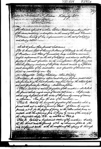
The Schedule referred to in these Letters Patent and making part of the same, containing a description in the words of the said Samuel P. Mason himself of his improvement, in the art of whipping and cleaning cotton.
To all to whom these presents shall come:
Be it known that I Samuel P. Mason of Killingly in the County of Windham and State of Connecticut have invented a new and useful improvement in the art of whipping and cleaning cotton preparatory to the next operation in its manufacture or picking; and that the following inclusive of the plates hereto annexed is a full and exact description of the construction and operation of the said machine as invented by me viz
Horizontal Rotary Stationary Cotton Whips
A machine for whipping cotton and cleaning it from seeds & dirt also for breaking the hard bunches very fine, leaving the cotton light and well prepared for Packing. Ascertained as follows.
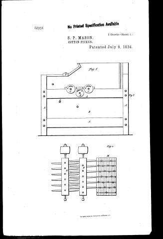
Plate 1. Exhibits a vertical projection of the machine A. A. A. A. the frame which may be made of wood or cast iron — B. B. B. B. which may be fastened to the sides of the frame by means of screws or rivets — C. the form the sides of the machine.
Plate 2. Exhibits the horizontal projection of the machine which is formed with and in which is formed a throat — D. between the angular panels a. v. b. for the purpose of feeding in the cotton which comes in contact with the stationary pins or fingers by means of the extremity of the horizontal shafts C. C. as exhibited on Plate 1.
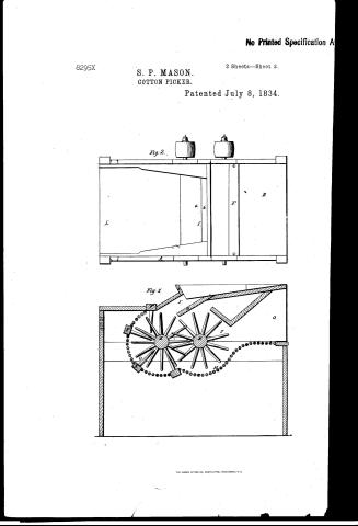
Plate 3. Exhibits a longitudinal section of the machine. (See what is the throat and the frames a. v. b. as shown on Plate 2. the only difference being with the exception of the opening C through
Page 4.
7/8/1834 8295X
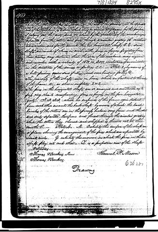
which the cotton passes the scraper at the end of the grooves. At the opposite end of the machine is a door which may be opened at pleasure for the purpose of taking out the dirty seeds &c which by the operation of the machine are separated from the cotton and pass through a circular grating 16, conducted under and partly around the two horizontal shafts E. & C. said shafts are made of strong iron rods with pins or fingers projecting from their centres any distance that the size of the machine may require and revolve with a velocity of 1500 to 2000 revolutions per minute in the direction of the arrows or pulleys C. C. — Plate 1, by means of a belt passing round said pulleys and over binding pulley D. The journals of the shafts run in boxes which are fastened to the side of the frame A, as shown on plates 1 & 2.
The pins in the horizontal shafts are so arranged and constructed as to pass very close to corresponding pins or fingers in the four horizontal grooves F, F, F, F, which lie on the sides of the frame equi distant from each other around the back shaft, by means of which the hard bunches of the cotton are in the process broken very fine and the dirt and seeds separated therefrom and forced through the circular grating while the cotton thus cleaned and whiffled is thrown out at the mouth C. — Plate 4, M. Exhibits the surface of the shaft on a plane showing the arrangement of the pins which are represented by small circles. Y. exhibits the manner in which the pins in the two shafts play into each other. Z. is a perspective view of the shaft.
Witnesses
Thomas Backus, Jr.
Thomas Backus
Samuel P. Mason
636 h. 87
Drawing
Published accounts: journal notice
Notice in the monthly list of patents, with remarks
Journal of the Franklin Institute, new ser., vol. 15 (1835), p. 95 · View the page
5. For a Cotton Whipping Machine; Samuel P. Mason, Killingly, Windham county, Connecticut, July 8.
Remarks. The patentee has described this machine entirely by references to the drawings, without putting in any claim to novelty, or designating, in any manner, the difference between it and other whipping, or batting, machines. It operates by means of two horizontal shafts, furnished with fingers, or projecting pins, which play between each other, those passing through one, coming nearly into contact with the other, shaft. There are also some stationary pins, or fingers, attached to the box in which the shafts revolve, serving to aid them in their operation.
Published accounts: journal notice
Notice in the monthly list of patents, with remarks
Journal of the Franklin Institute, new ser., vol. 15 (1835), p. 96 · View the page
The description of this plough is given, with the precise measurements of the various parts, and with references to lines laid down in the drawings, for the purpose of showing and explaining that particular shape of the mould board, and other parts, which the patentee thinks best adapted to the separation of the furrow slice; and the claim made is to a plough constructed exactly upon the principles described. A description and claim of this kind do not fulfil the requirement of the patent law, that the inventor should distinguish his invention from all things before known or used. 11. For a Plough; James Jacobs, Maysville, Mason county, Kentucky, July 8.
Remarks. This the patentee denominates the "Smeller Plough," and says, "My claim is particularly laid for the formation of my mould board, according to the several lines described on the face thereof, which, by the assistance of the several perpendiculars let fall from them, give those parts of circles, or segments, by or according to the courses of which, the various concavities and convexities of my said board are formed. I also claim the formation of the head and neck, as giving it the advantage of being cast in one piece, with the rest of the mould board, at one operation, without the necessity of a pattern made in two pieces; and more particularly because it allows the holes for the front bolt, and for the brace likewise, to be cast at the same time with the rest." The casting of the head and neck in one piece with the mould board, is a common practice; the other claims are indefinite.
About this record
- Patentee
- DATAMP
- Date
- the Name and Date index of patents, DATAMP, USPTO records
- Invention
- DATAMP
- Listed in
- the Name and Date index of patents, DATAMP, USPTO records, Jim Shaw's X-patent list, the Journal of the Franklin Institute, Burke's List of Patents (1847)
- Burke's 1847 Patent Office list gives the same patent.