

Drawings and documents
National Archives restored drawings: drawing
Capt. J.D. Woodside's Patent Drawing for a Pump or Ship Gauge

National Archives, Restored Patent Drawings (Record Group 241) · Full-size scan at the National Archives · Catalog record
Show the text on the drawing Hide (427 words)
Words on the drawing as machine-read by the National Archives; not checked. Useful mainly for searching.
73. MEASURING INSTRUMENTS. / TS. / Water Gages: Float. / apt. J. D. WOODSIDE'S / 11- / PATENT PUMP OR SHIP GUAGE, / # 8317x / For Measuring correctly the Depth of Water in the Hold of a Vessel. / Pated 14 July. 1834. / DIRECTIONS / REFERENCES. / For attaching the Guage to the Pump. / A. A portion of the Pump. / B. A portion of the upper band. / The brass frame or closet, containing the cylinder over / C. The small brass box a. the door; b. the hasp; / which the graduated tape passes, must be let into the out- / side square of the pump just below the upper band. A / c. hole for hasp; d. key-hole. / groove must then be cut deep enough, long enough, and / 0 d c / D. Barrel or cylinder over which the tape passes. / wide enough to receive the graduated part of the tape, say / from 4 to 6 feet below the case. Over this groove a piece of / E. Groove in which the tape moves. / sheet copper must be secured to shield and keep the tape in / its place. / 39 / F. Tape graduated to inches and half inches. / G. Float which works in a board casing. / From the heel of the pump to within a foot or two of this / groove, there must be attached a square casing made of 12 / H. Connecting wire. / inch stuff, 2 inches square in the clear, for the float to play / I. Weight to take up the slack of the tape. / in. As the water rises and falls in the pump-well, the float / will move accordingly. / K. The friction roller. / This float may be connected with the tape by a piece of / small brass or copper wire. / 41 / When these arrangements have been made, and the pump / is in its place, the regulation of the guage depends upon the / depth of water in the hold of the vessel, which depth must / be accurately ascertained this being done, the guage is com- / plete, and will most assuredly designate at all times the / 42 / depth of water in the hold of the vessel. / N. B. The above-named instrument has been patronized / by the commissioners of the Navy and others. Merchants / and masters of vessels who are disposed to adopt the use of / it, will please to address the subscriber and patentee, post- / 43 / paid, Washington, D. C. and those who may wish to pur- / chase a Right for one or more ports, will please address me / as above directed. / J. D. WOODSIDE, Patentee, / WASHINGTON, D. C. August 9th, 1834. / 44 / 45 / CLASSIFICATION / 8317 X / 46 / DIV ISION. / 47 / 48 / G K
USPTO scan
The patent as scanned by the USPTO
-
 Page 1
-
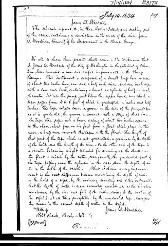 Page 2


U.S. Patent and Trademark Office · Google Patents
Show the transcription Hide (425 words)
Machine transcription (LightOnOCR) of the pages as scanned by the USPTO, most of them the handwritten copies made when the records were restored after the 1836 fire. Not checked; it can misread handwriting, so compare it with the scan.
Page 1.
8317X
J. D. Woodside.
Water Gauge.
Patented Jul. 14, 1834.

Page 2.
7/14/1834 8317X
July 14, 1834 209.
James D. Woodside.
The schedule referred to, in these Letters Patent, and making part of the same, containing a description in the words of the said James D. Woodside, himself, of his Improvement in the Pump Gauge.
To all to whom these presents shall come: Be it known that J. James D. Woodside of the City of Washington in the District of Columbia, have invented a new and useful improvement in the Pump Gauge. This instrument is composed of a small brass box or case of about two inches long, one and a half inch wide, and one inch deep, with a door and lock, containing a barrel or cylinder of half an inch diameter, let into the pump, just below the upper band, over which a tape passes, from 4 to 6 feet of which is graduated in inches and half inches. This tape extends down a groove in the side of the pump, so far as it is graduated, the groove is covered with a strip of sheet iron. The tape then passes into a board casing of about two inches square in the clear, about four or six feet from a float which plays in this case, a brass wire connects the tape with the float. The length of that part of the tape which is not graduated, is governed by the depth of the hold, and the length of the wire. On the other end of the tape is a counter balancing weight intended for drawing up the slack as the float is raised by the water, consequently the graduated part of the tape passing over the cylinder in the case, shows the depth of water in the hold of the vessel. What I claim as my improvement is the vast difference between ascertaining the depth of water in the hold of a vessel, by the ordinary sounding rod, & this instrument—that the depth of water is more accurately ascertained, as the vibration occasioned by the rise and fall of the water, owing to the motion of the vessel, is at all times perceptible by the graduated tape, therefore the mean is the correct depth of water in the vessel.
Witness
Robert Clarke, Charles Hill
[337000]
James D. Woodside
[Signature]
Published accounts: journal notice
Notice in the monthly list of patents, with remarks
Journal of the Franklin Institute, new ser., vol. 15 (1835), p. 102 · View the page
27. For a Pump Gauge, for ascertaining the depth of the water in the hold of a vessel; James D. Woodside, city of Washington, District of Columbia, July 14.
Remarks. An opening is to be made in the side of a ship's pump, just below the upper band, to receive a small brass box, which may be two inches high, and one and a half wide, and which is to be furnished with a door, to close the opening when the gauge is not in use. A small roller crosses the upper end of the box, and over this passes a tape, graduated into inches and half inches. One end of this tape descends through a casing, nearly to the bottom of the hold, and has a float suspended to it, which will be buoyed up by the water. To the other end of this tape, a counter weight is attached, to take up the slack, by drawing the tape over the roller as the float rises in the water. The patentee says, "What I claim as my improvement, is the vast difference between ascertaining the depth of water in the hold of a vessel by the ordinary sounding rod, and this instrument; that the depth is more accurately ascertained, as the vibration occasioned by the rise and fall of the water, owing to the motion of the vessel, is at all times perceptible by the graduated tape; therefore the mean is the correct depth of water in the vessel." This claim is very awkwardly expressed, as it is not made for the improved instrument as described, but for the vast difference between the result obtained by it, and by the ordinary means used for the same purpose; and this is claiming the effect of a machine, instead of the machine itself.
About this record
- Patentee
- DATAMP
- Date
- the Name and Date index of patents, DATAMP, USPTO records
- Invention
- DATAMP
- Listed in
- the Name and Date index of patents, DATAMP, USPTO records, Jim Shaw's X-patent list, the Journal of the Franklin Institute, Burke's List of Patents (1847)
- Burke's 1847 Patent Office list gives the same patent.