

Drawings and documents
National Archives restored drawings: drawing
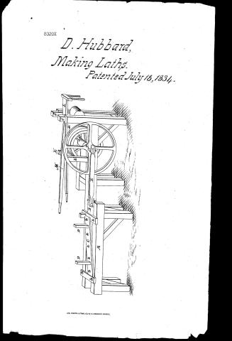
Dana Hubbard's Patent Drawing for a Lath Machine

National Archives, Restored Patent Drawings (Record Group 241) · Full-size scan at the National Archives · Catalog record
Show the text on the drawing Hide (216 words)
Words on the drawing as machine-read by the National Archives; not checked. Useful mainly for searching.
144, WOOD WORKING MACHINES. / Slicers, Reciprocating. / Machine / DANA HUBBARD'S / ASSI. ICATION / lath MACHINE . / 8320.X / Patented 18th July. 1834. / DIVISION. / J. / K. / M. / J. / D. / D. / F. / C. / E. / di / A. / REFERENCES. / A, The frame, with rabbits, or grooves on the inner top side. / B, A plank, which slides, or works in the grooves of the frame, and to which is secured, a knife, by botts. / 19 / C, A Guide, to the under side of which is secured a plate of iron, about 1/4 inch thick, stationary. / D,D, Two uprights, to support the plank from which the laths are to be cut. / E, A pitman, to give motion to the plank and knife, by which the laths are to be out. / F, A fly wheel, to which the pitman is attached by a wrist. / G, Pulley, by which the Machine is to be propelled. / H, The loose pulley. / I, Pulley, for tightening the band. / Scale / J,J, A gate, to which the tightening pulley is attached. / Half an inch to the foot. / K.K. Two uprights, to which the band guides are attached. / L, A guide, for shifting the band. / M, A lighter staff to the tightening pulley. / From a delached drawing / bB
USPTO scan
The patent as scanned by the USPTO
-
 Page 1
-
 Page 2
-
 Page 3
-
 Page 4


U.S. Patent and Trademark Office · Google Patents
Show the transcription Hide (1,236 words)
Machine transcription (LightOnOCR) of the pages as scanned by the USPTO, most of them the handwritten copies made when the records were restored after the 1836 fire. Not checked; it can misread handwriting, so compare it with the scan.
Page 1.
8320X
D. Hubbard,
Making Laths.
Patented July 18, 1834.

A.M. PHOTO-LITHO. CO. N.Y. (OSBORNE'S PROCESS)
Page 2.
7/18/1834 8320X
July 18, 1834
Dana Hubbard, Whiting, Virginia
Letters Patent
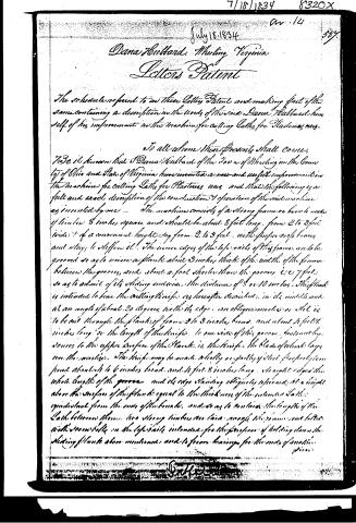
The schedule referred to in these Letters Patent and making part of the same containing a description in the words of the said Dana Hubbard himself of his improvement in the machine for cutting Laths for Plasters uses.
To all whom these Presents shall come,
Be it known that I Dana Hubbard of the Town of Whiting in the County of Ohio and State of Virginia have invented a new and useful improvement in the machine for cutting Laths for Plasters uses, and that the following is a full and exact description of the construction & operation of the said machine as invented by me — The machine consists of a strong frame or bench made of timbers 6 inches square and should be about 8 feet long, from 2 to 3 feet wide, & of a convenient height say from 2 to 3 feet, with the proper use of braces and stays to stiffen it. The inner edges of the top rails of this frame are to be grooved so as to receive a plank about 3 inches thick of the width of the frame between the grooves, and about a foot shorter than the grooves, i.e. 7 feet so as to admit of its sliding endwise the distance of 5 or 10 inches. This plank is intended to bear the cutting knives as hereafter described, in its middle and at an angle of about 20 degrees with its edge, an oblique motion or slot is to be cut through the plank of from 2 to 3 inches broad, and about 4 feet 8 inches long, or the length of the knife, to one side of this groove, fastened by screws to the upper surface of the Plank, is the knives, the blade of which lays over the motion. The knives may be made wholly or partly of steel, properly tempered about 1 to 6 inches broad, and 4 feet 8 inches long, straight edged the whole length of the groove and its edge standing obliquely upward at a height above the surface of the plank equal to the thickness of the intended Laths, equidistant from the ends of the bench, and so as to contain the length of the Lath between them. Two strong timbers are laid across the frame and fitted with screws into the top rails intended for the purpose of holding down the sliding plank above mentioned and to secure bearings for the ends of motion.
Signed
Page 3.
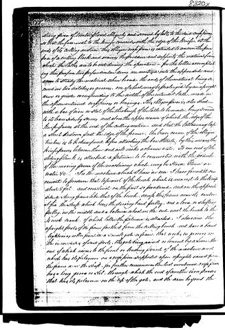
strong piece of timber placed obliquely and secured by bolts to the said orifice so that the face next to the knife coincides with the edge of the knife at the ends of its cutting motion. This oblique orifice is intended to assume the form of a cutting block and receive the pressure and support the material from which the laths are to be cut during the operation—for the better accomplishing this purpose two perpendicular arms are mortised into the upper side and appear to steady the material when broad, the ends of the material being secured in two notches or grooves, one of which may be prolonged by an upright arm or guide corresponding to the width of the intended laths, made in the aforementioned orifices or bearings. This oblique piece is also short—with a bar of iron or steel of the thickness of the laths to be made, being secured to its lower side by screws and above the appearance of which the edge of the knife passes at the end of the cutting motion, and that the laths may lap a short distance past the edge of the former, the lower corner of the oblique timber is to be chamfered before attaching the bar thereto, by this means the knife passes between them and will make a cleaner cut. To one end of the sliding plank is attached a piston to be connected with the crank of the moving power of the machinery which may be Horse, Steam or Water &c. In the machine which I have in use I have found it convenient to produce that to several of the bench which is nearest to the knife about 8 feet, and continue on the part so produced, and on the opposite side a long frame like that of the bench, across this frame near its centre is fixed the shaft which bears the sliding band pulley, and a loose or shifting pulley in the middle and a balance wheel on the end next the bench to the 4 inch crank, of which latter the piston is attached. I also raise the upright posts of the frame farther from the cutting bench and have a band tightening roller fixed in a double gate or frame, that works in grooves on the inner sides of said posts, the gate being raised or lowered by a lever, the one of which comes to the front or leading point of the machine and which has its piston on a cross piece supported upon uprights raised from the frame near the shaft, for further convenience the last mentioned cross piece has a long groove or slot, through which the end of another lever passes that has its piston on the top of the gate, and the arm beyond the
Page 4.
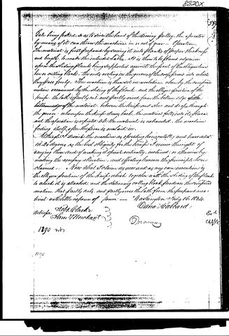
Gate being fastened so as to secure the band of the driving pulley, the operator by means of it can throw the machine in or out of gear.
The material is first prepared by sawing it into planks of proper thickness and length, to make the intended laths, and is then to be placed edgewise upon the sliding plank being supported against the front of the oblique knife or cutting block. The ends resting in the grooves of the cross pieces into which they pass freely. The machine is then set in motion, when by the compound motion occasioned by the sliding of the plank, and the oblique position of the knife, the lath is partly cut and partly raised from the bottom edge of the bottom edge of the material, between the knife and block, and drops through the groove, whereupon the knife draws back, the material falls into its place, and the operation is repeated till the material is exhausted, the machine feeding itself after the piece is overlaid in.
Although I describe the machine as operating horizontally, and have selected 20 degrees as the best obliquity for the knife, I reserve the right of varying them, and of making it operate vertically, inclined, or otherwise by making the necessary alteration, and effecting however the principle here claimed.
Now what I claim as new and as my own invention is the oblique position of the knife, which, together with the sliding of the plank to which it is attached, and the stationary cutting block, produces the compound motion, that partly cuts, and partly raises the lath from the prepared material, with little expense of power.
Washington July 16, 1834
Dana Hubbard
Witnesses:
Robt. Clarke
Sam Merchant
1790
1190
Published accounts: journal notice
Notice in the monthly list of patents, with remarks
Journal of the Franklin Institute, new ser., vol. 15 (1835), p. 105 · View the page
34. Fora machine for Cutting Laths; Dana Hubbard, Wheeling, Ohio county, Virginia, July 18.
Remarks. A plank, of about eight feet in length, is to be fixed so as to slide backward and forward, horizontally, in grooves made for that purpose, in a strong bench or frame. The plank is to receive its traversing motion of about eight inches, from a pitman, or shackle bar, attached to one end of it, which is acted upon by a crank on a fly wheel shaft. A knife, the full length of a lath, and from four to six inches wide, is to be fixed upon the sliding plank obliquely, making an angle of about twenty degrees with the edge thereof. The stuff to be cut is first sawed into boards, and then cross-cut to the length of a lath; these boards are dropped edgewise into a groove, falling so as to be cut by the knife, the board bearing against a cutting block, faced with steel on its under side. The laths pass, as they are cut, through an opening made in the plank for that purpose. The claim is to "the oblique position of the knife, which, together with the sliding of the plank to which it is attached, and the stationary cutting block, produces the compound motion that partly cuts, and partly rives, the lath from the prepared material, with little expense of power." An oblique position has been repeatedly given to knives for cutting laths, and this, therefore, standing alone, is not the proper subject of VOL. XV. No. 2.-FEBRUARY, 1855. 14 a claim; we think, therefore, that this part might have been advantageously altered; the general construction and arrangement of the machine are, probably, sufficiently novel to justify a patent, although none of its individual parts are new.
DATAMP: illustration
Illustrations from DATAMP


DATAMP (Directory of American Tool and Machinery Patents), via the Internet Archive · Archived DATAMP page
About this record
- Patentee
- DATAMP
- Date
- the Name and Date index of patents, DATAMP, USPTO records
- Invention
- DATAMP
- Listed in
- the Name and Date index of patents, DATAMP, USPTO records, Jim Shaw's X-patent list, the Journal of the Franklin Institute, Burke's List of Patents (1847)
- Burke's 1847 Patent Office list gives the same patent.