

Drawings and documents
National Archives restored drawings: drawing
Joel Woodell's Patent Drawing for a Blacksmith's Striker

National Archives, Restored Patent Drawings (Record Group 241) · Full-size scan at the National Archives · Catalog record
Show the text on the drawing Hide (101 words)
Words on the drawing as machine-read by the National Archives; not checked. Useful mainly for searching.
78. METAL FORGING. / Olivers / fal Hoodel / 702.19.7.57. / Blacksmiths Striker / Catented 6."Augi 1834, / CLASSIFICATION / 8344-X / DIV ISION. / References, / A.Frame, B. front cylinder, / D.Back " / elve, F, hammer, G small ironlever, / plate, I. chain cometing cylinders, / meeting crank with leverL, M,treadle, / princs be tween posts. O, transverse spring / spring" "connected bychain to O, / N' / Q. anoil. K. spring rabbit". / Patent office / were you! / Made under the direction of the / of Patents in conformity with the Act of 3. march 3. 1527 / Hd Sumorth / 11 / Commissioner of Patents.
USPTO scan
The patent as scanned by the USPTO
-
 Page 1
-
 Page 2
-
 Page 3
-
 Page 4


U.S. Patent and Trademark Office · Google Patents
Show the transcription Hide (1,061 words)
Machine transcription (LightOnOCR) of the pages as scanned by the USPTO, most of them the handwritten copies made when the records were restored after the 1836 fire. Not checked; it can misread handwriting, so compare it with the scan.
Page 1.
8344X
J. WOODDEL.
Oliver.
Patented Aug. 6, 1834.
THE NORRIS PETERS CO., PHOTO-LITHO., WASHINGTON, D. C.
Page 2.
8/6/1834 8344X
Aug. 6, 1834
J. C. Model, Jackson Tennessee.
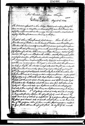
Letters Patent August 6, 1834.
The Schedule referred to in these Letters Patent and making part of the Same containing a description in the words of the said J. C. Model himself of his improvement in hammering iron by a machine constructed to supply the place of a common hand as a striker.
To all to whom these presents shall come. Know ye that I J. C. Model of Jackson in the County of Madison and State of Tennessee Blacksmith have invented and constructed a new and useful improvement in the art of hammering iron on the anvil by a machine to supply the place of a striker with a common Pledge hammer. Called by the inventor the improved Blacksmiths striker. And the following is a full and perfect description of the plan construction and operation of said machine.
1st. A ground frame composed of four rails braced and morticed to connect them in nearly a square. The longest or side rails about three feet and an half in length. The shortest or cross rails about two feet six inches. All of them from six to nine inches square so as to give strength and weight.
2nd. Four upright posts braced into the rails flush with the outside but so far from the ends as to occupy a station about one foot six inches apart. The projecting ends of the rails will keep the frame steady. The front and the ends next the anvil about 3 inches square and 2 feet 6 inches high. The corners or two back posts about the same size but 3 feet four inches in height. Braces and cross bars can be placed on the hindmost uprights here also to throw in front. These braces can be placed according to the fancy of the builder.
3rd. A cylinder about 4 inches diameter to occupy a horizontal position between the upright posts near the anvil the right hand end of which is supported by a gudgeon passing through the front and turned into a crank which returns with a bend to the line of the gudgeon when it forms another point or gudgeon as required by a framework on the upright post. The length of the crank
Page 3.
from its centre is about six inches. The other end of the cylinder is supported by a guigeam in the left hand foot. A 4th another cylinder resting on guigeams also placed horizontally but between the back up right foots. This cylinder is about 5 or 6 inches diameter swelled at the foot of it where the hammer hole passes through it.
5th A Pledge Hammer on a helve about four feet long set into the last described cylinder near the left hand end of it. This helve is made to move round upon a journal so as to move the head or face of the hammer to the anvil a small iron bar set into the helve at the cylinder moves it round and by notches in the metallic plate placed on the cylinder holds the hammer to its position a small spring holds the bar in the notch it is wanted to occupy.
6th A chain connected to the last mentioned cylinder at the under side by a staple is thence brought up over it and carried forward to the next or front cylinder over it also and by a hook fastened at the bottom or under side by the hook the chain can be tightened so as to keep the working foots connect and prevent sliding.
7th a rod or chain connecting with the crank and extending down to near the ground as fastened to a lever. This lever is of wood and is placed parallel with the longest side; it is about four feet long fastened by a foot at the end remote from the anvil the other end to move up and down as a support of a treadle which crosses at right angles joining in front of the anvil block has the left hand end of it in a position to receive the foot of the smith the right hand end is fastened by a foot like the lever.
8th 4 Springs 2 crossing between the upright foots. The ends let into them one of each is placed under each cylinder. The third is a transverse spring the end near the anvil block rests upon the spring between the front foots passing under the spring between back foots and its remote end is connected by a short chain to the last spring which is set into the cylinder which holds the hammer. The springs are adjusted so as to keep the hammer at its elevation, in which the stroke is directed. A spiral spring of metal may be used instead of the three first springs by fastening
Page 4.
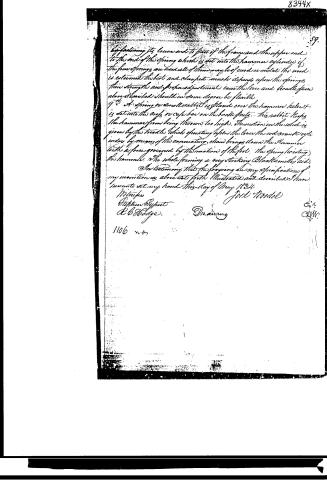
by fastening its lower end to that of the frame and the upper end to the end of the spring which is set into the hammer cylinder if the four springs are used all of them may be of wood or metal; the wood is esteemed the best and cheapest, much depends upon the springs, their strength and proper adjustment even the lever and headpiece above described should in some degree be flexible.
9th. A spring or small rabbit is placed over the hammer, which is set into the legs or case bar on the back foot. This rabbit keeps the hammer from being thrown too high. The motion in the whole is given by the treadle which operating upon the lever the rod or arm cylinder by means of the connecting chain brings down the hammer with a force generated by the motion of the foot. The spring holding the hammer. The whole forming a very striking Blacksmith's aid.
In testimony that the foregoing are my specifications of my invention as above set forth illustrated and described I have hereunto set my hand this day of May 1834.
Witness
Stephen Peppin
A. B. Hodge.
Drawing
1106 no.
Jock Woodell
E. A.
C. J. W.
8344X
Published accounts: journal notice
Notice in the monthly list of patents, with remarks
Journal of the Franklin Institute, new ser., vol. 15 (1835), p. 184 · View the page
8. For a Blacksmith's Striker; Joel Woodel, Jackson, Madison county, Tennessee, August 6.
Remarks. The apparatus described and figured as the subject of this patent, is so similar to that patented by Mr. Lewis Stripe, of North Carolina, and described at p. 172, vol. xiii., that we do not see how it can stand in law, unless patents can be obtained for each of the states individually, and each of them can find a true and original inventor of the same thing. This striker has become the subject of altercation between two previous patentees, and if the declarations made by persons claiming to be informed on the subject, are worthy of credit, the invention is much older than either of their patents, having been long known and used in North Carolina. The present patentee does not prefer any claim.
About this record
- Patentee
- DATAMP
- Date
- the Name and Date index of patents, DATAMP, USPTO records
- Invention
- DATAMP
- Listed in
- the Name and Date index of patents, DATAMP, USPTO records, Jim Shaw's X-patent list, the Journal of the Franklin Institute, Burke's List of Patents (1847)
- Burke's 1847 Patent Office list gives the same patent.