

Drawings and documents
National Archives restored drawings: drawing
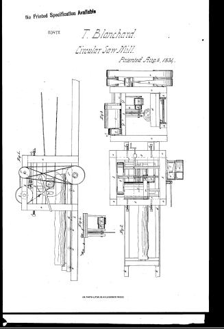
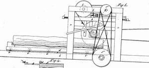
Thomas Blanchard's Patent Drawing for a Shifting Circular Saw Mill


National Archives, Restored Patent Drawings (Record Group 241) · Full-size scan at the National Archives · Catalog record
Show the text on the drawing Hide (224 words)
Words on the drawing as machine-read by the National Archives; not checked. Useful mainly for searching.
Sheet 1. #4- / Saw mills. On / 143, WOOD SAWING. / Circular Saw / MILLS, / 110. SAWS. / [130] / 143. WOOD SA WING, / Thomas Blanchard / Plate I / Circular Saw / CLASSIFICATION / 8347-8 / Shifting Circular law Mill. / Vol. is hg.85 / DIVISION. / Patented aug.8th 1834. / Sign. / d h / References. a a.aa h posts. bbx. beams girders. c.e ways. d carriage e lack (datedia).fffinionsdated. / g. saw carriage. see Fig. 2. h h. ways for the i pulley on the K a smaller pulley. / B drum. m belt connecting K α.h.- n small pullez on drumshaft. o a pulleys on the double pulley shaft p. / belt connecting n.K.o. rx pulleys. s'i" pulleys on the pinion shaft f. t crop band connecting xx. / u band connecting v tightening pulley, w zack and pinion to move the Jaw carriage sideways. / x index plate stationary pin. ZZ guides. i.i. ii serews to adjust the saw e'e'e' wheels. / sig 1. Inderview. Fig 2. Top view. Fiy.3. Frontview. ofigh faw Patent affiee Dee 29.. 1841 / made under the direction of the Commispioner of Patents / VIII / in conformity with act of 3. 1837. / ML ellmorth / M.L. Slindamann del. / form proner afidate
Sheet 2. Plate / II / 110. SAWS. / [130] CircularSawMills / Vol. is is py. m. 85. / Jiy.3. / be / Jj.2. / HIM / e' / NOISIAIT / +-LTIES / ircular Saw Mills / ONLM VS ДООМ 821
USPTO scan
The patent as scanned by the USPTO
-
 Page 1
-
 Page 2
-
 Page 3
-
 Page 4


U.S. Patent and Trademark Office · Google Patents
Show the transcription Hide (1,013 words)
Machine transcription (LightOnOCR) of the pages as scanned by the USPTO, most of them the handwritten copies made when the records were restored after the 1836 fire. Not checked; it can misread handwriting, so compare it with the scan.
Page 1.
No Printed Specification Available
8347X
T. Blanchard.
Circular Saw Mill.
Patented Aug. 8, 1834.
AM. PHOTO-LITHO. CO. N.Y. (OSBORNE'S PROCESS)
Page 2.
Aug. 8, 1834 85. 8347X
Thomas Blanchard, of the City of New York.
Letters Patent.
The schedule referred to in these Letters Patent and making part of the same containing a description in the words of the said Thomas Blanchard himself of his improvement in the saw mill, which he calls Blanchard's shifting circular saw mill.
To all to whom these presents shall come
Be it known that I Thomas Blanchard of the City of New York in the county and State of New York, have invented a new and useful improvement in the saw mill for sawing lumber, which I call Blanchard's Shifting circular Saw Mill, of which the following is a full and exact description viz.
A wooden frame may be made consisting of four parts eight feet high, six feet apart connected together with proper girders & beams at top and bottom, Inside of this frame at the bottom, are ways on which a carriage runs of sufficient length for the lumber to be sawed, on the under side of said carriage is a rack with the cogs or teeth downwards, into this rack, a pinion wheel plays, which gives the carriage a steady horizontal motion like an ordinary saw mill carriage, Above the log carriage at a proper distance is a saw carriage which may be made of iron, and sufficient width and length to contain the saw and saw arbor. This carriage is made to move freely in grooves made in ways made fast to the four parts of said frame, the motion of the saw carriage must be at right angles with the log carriage and is moved at every cut of the saw, to give the board to be sawed its proper thickness, On one of the saw arbor is a pulley which gives motion to the saw by the side of which is a small pulley which conveys a reverse motion
Page 3.
to the log carriage by belts... a belt passing around it and three rounds a large pulley or drum on a shaft on the top of said frame. On the other end of said shaft is a small pulley which gives motion to a second shaft on top of said frame on which is a larger pulley. On the end of said second shaft, on the top of the frame is a double-pulley directly over a double pulley of large size on the pinion shaft which is under the log carriage. These pulleys are driven by two belts: the one crooked, the other running upon a tightened pulley is made to bear against the crook belt while the log carriage is moved towards the saw in the operation of sawing, and to reverse the motion and bring the carriage back, the tightening pulley is borne against the other, belt which causes the crook belt to slide over the pulley and gives the pinion shaft a reversed motion. The saw carriage may be moved occasionally by a hand crank and geared work or otherwise; the distance of moving the saw carriage to give the proper thickness to the board to be cut is fixed by an index plate in which holes are made of the proper distance apart for the thickness of the board to be sawed. This plate is connected at one end to the saw carriage, at the other end to a stationary pin which will enter into the holes of the index plate, and as often as the saw cuts a board from the log the index plate is moved so that the said stationary pin may enter the next proper hole; and thus the boards will all be of equal thickness. Guides may be placed at each side of the saw, made fast to the saw carriage, and as near the saw as possible, without producing friction, which will prevent the saw from having a tremulous motion. There must be set screws to adjust the saw carriage, so as to give the saw a straight forward direction, as it passes through the operation of cutting, and thus vary the inclination of the saw as it makes to or from the log. This apparatus in
Page 4.
88
further compliance with the Law describe the character or principle which constitutes his invention or improvement distinguishing it from others of the same kind known and used before. The principle of this invention consists of the combination of a circular saw upon a shifting carriage, with a common saw mill log carriage of any convenient construction the said shifting carriage being made to slide at right angles with the log carriage, the thickness of the board, plank, or other lumber to be cut, and to be firmly fixed in its position always during the action of the machine substantially as the same is above described. Circular saws are not claimed by this applicant, nor the construction of circular saw upon shifting or sliding carriage, nor does he claim a patent for the particular construction of the said shifting carriage, nor the index whereby the extent of its lateral motion may be adjusted and fixed but the invention which he claims as his, consists, as aforesaid, of the combination of a circular saw on a shifting carriage, constructed substantially as aforesaid in any convenient form, and capable by any convenient means of being shifted and fixed as aforesaid in operation with a log carriage of any convenient construction differing from the common and known saw mill in this, especially, that the saw in these is not made to shift but the log is shifted in its carriage according to the thickness of the lumber to be sawed.
Witnesses
Henry Rogers Junr
Saml. M. Richards
Thomas Blanchard
Filed 11.9.6.
Published accounts: journal notice
Notice in the monthly list of patents, with remarks
Journal of the Franklin Institute, new ser., vol. 15 (1835), p. 186 · View the page
13. For an improvement in the construction of the Saw Mill; Thomas Blanchard, city of New York, August 8.
Remarks. A circular saw is to be used to cut the timber, which timber is to be fixed upon a carriage, constructed and moving in the manner of the common saw mill carriage. The shaft of the saw runs in gudgeons upon a sliding frame, which is so constructed as to allow of its being shifted transversely to the carriage, in order to obviate the necessity for moving the log laterally, after a cut has been made. The different movements required are to be communicated by means of bands and whirls. "The principle of this invention consists of the combination of a circular saw with a common saw mill log carriage, of any convenient construction; the said shifting carriage being made to slide at right angles with the log carriage; the thickness of the boards, plank, or other lumber to be cut, and to be firmly fixed in its position during the action of the machine, substantially as the same is above described. Circular saws are not claimed by this applicant, nor the construction of circular saws upon shifting or sliding carriages; nor does he claim a patent for the particular construction of the said shifting carriage, nor the index whereby the extent of its lateral motion may be adjusted and fixed. But the invention which he claims consists, as aforesaid, of the combination of a circular saw on a shifting carriage, constructed substantially as aforesaid, in any convenient form, and capable, by any convenient means, of being shifted and fixed in operation with a log carriage of any convenient construction; differing from the common and known saw mill in this especially, that the saw in these is not made to shift, but the log is shifted in its carriage, according to the thickness of the lumber to be sawed."
DATAMP: illustration
Illustrations from DATAMP

DATAMP (Directory of American Tool and Machinery Patents), via the Internet Archive · Archived DATAMP page
About this record
- Patentee
- DATAMP
- Date
- the Name and Date index of patents, DATAMP, Burke's List of Patents (1847)
- Invention
- DATAMP
- Listed in
- the Name and Date index of patents, DATAMP, USPTO records, Jim Shaw's X-patent list, the Journal of the Franklin Institute, Burke's List of Patents (1847)
- The sources give different dates; the date shown is the one most of them agree on.
- The Franklin Institute's journal confirms the date shown.
- Burke's 1847 Patent Office list gives the same patent.