

Drawings and documents
National Archives restored drawings: drawing
Thomas C. Chandler's Patent Drawing for a Fire Engine

National Archives, Restored Patent Drawings (Record Group 241) · Full-size scan at the National Archives · Catalog record
Show the text on the drawing Hide (36 words)
Words on the drawing as machine-read by the National Archives; not checked. Useful mainly for searching.
CLASS 103. PUMPS, / 181 / Solid Reciprocating Piston. / Multiple Cylinder / CLASSIFICATION / 8351.+ / DIVISION. / 50 / Patented Aug 9th 1834. / ThomasA. Chandler's Fire Engine / ПЛЛ / UULL / 4. / 15. / 6. / 14 / 16 / 10. / 10. / for / lp
USPTO scan
The patent as scanned by the USPTO
-
 Page 1
-
 Page 2
-
 Page 3
-
 Page 4


U.S. Patent and Trademark Office · Google Patents
Show the transcription Hide (1,039 words)
Machine transcription (LightOnOCR) of the pages as scanned by the USPTO, most of them the handwritten copies made when the records were restored after the 1836 fire. Not checked; it can misread handwriting, so compare it with the scan.
Page 1.
8351X
T. A. Chandler.
Fire Engine.
Patented Aug. 9, 1834.
Page 2.
Aug. 9, 1834
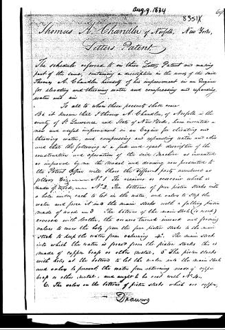
Thomas A. Chandler of Norfolk, New York,
Letters Patent.
The schedule referred to in these Letters Patent and making part of the same, containing a description in the words of the said Thomas A. Chandler himself of his improvement in an Engine for elevating and throwing water and compressing and expanding water and air.
To all to whom these presents shall come.
Be it known that I Thomas A. Chandler, of Norfolk in the county of St. Lawrence and State of New York, have invented a new and useful improvement in an Engine for elevating and throwing water, and compressing and expanding water and air and that the following is a full and exact description of the construction and operation of the said Machine as invented or improved by me the Model and drawing now presented to the Patent Office will show the different parts numbered as follows:
1. The receiver or reservoir which is made of wood.
2. The bottom of four piston stocks with a hole under each to let in the water, and valves to stop the water and force it into the main stock with a falling piston made of wood.
3. The bottom of the main stock (is used) covered with leather, the corners turned inward and forming valves to cover the hole from the four piston stocks to the main stock to keep the water from returning.
4. The main stock into which the water is forced from the piston stocks, this is made of copper brass or other metal.
5. The piston stocks with holes at the bottom to let the water into the main stock and valves to prevent the water from returning made of copper brass or other metal, and ought to be cast with a hole.
6. The valves on the bottom of piston stocks which are copper.
Drawing
Page 3.
70. 5351X
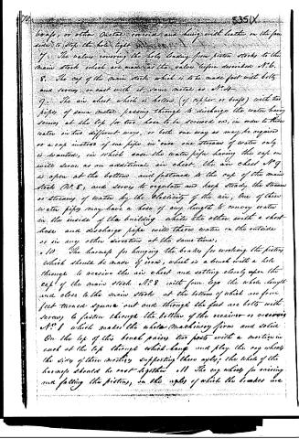
braps, or other metal covers and hung with leather on the far side to stop the hole tight.
7. The valves covering the holes leading from piston stocks to the main stock which are made as the valves before described N.6.
8. The cap of the main stock which is to be made fast with bolts and screws, or cast with it, same metal as N.4.
9. The air chest which is hollow (of copper or braps) with two pipes of same metal passing through to discharge the water having screws at the top for two holes to be screwed on, in order to throw water in two different ways, or both one way as may be required or a cap instead of one pipe in case one stream of water only is wanted, in which case the water pipe having the cap on will serve as an additional air chest, the air chest N.9 is open at the bottom and fastened to the cap of the main stock N.8, and serves to regulate and keep steady the stream or stream of water by the elasticity of the air, one of these water pipes may have a hose of any length to convey water in the inside of the building while the other with a short hose and discharge pipe will throw water on the outside or in any other direction at the same time.
10. The harness for hanging the brakes for working the pistons which should be made of iron, which is a bench with a hole through to receive the air chest and setting closely upon the cap of the main stock N.8 with four legs the whole length and close to the main stock at the bottom of which are four feet turned square out and through the feet are bolts with screws to fasten through the bottom of the receiver or receivers N.9 which makes the whole machinery firm and solid. On the top of this bench passes two posts with a mortice in each at the top through which hang and play the cog wheels the sides of these mortices supporting them axly; the whole of the harness should be cast together all. The cog wheels for raising and falling the pistons, on the axle of which the brakes are
Page 4.
8351X 71.
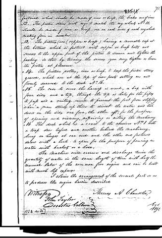
fastened which should be made of iron or brass, the brakes are given
12. The piston stems with cogs to match the cog wheel, No. 11,
should be made of iron or brass, one on each side of each cogwheel
making four in number.
13. The pistons (are) (copper or brass) having a movable cap at
the bottom which is fastened with copper or brass bolts and
screws to the upper part of the piston to secure and tighten the
packing so that by turning the screws you may tighten or loosen
the piston at pleasure.
14. The friction pulleys, iron or brass, to keep the piston strong
gears, which are at the top of iron posts setting on and
firmly secured to the deck No. 16.
15. The case to cover the harness is wood, a box with
four sides and a top, through the top is holes for the pipes
to pass and a railing round to prevent the foot from slipping
when a man stands up there to direct the water and two
doors on the side, one fore, the other aft, for the purpose
of opening and viewing, repairing or oiling the machinery.
16. The deck which is a cover to the receiver No. 1 with
a trap door before and another behind the machinery,
hung on hinges at one end and the other end fastened
down with a hook to open for the purpose of pouring in
water with buckets or a hose.
The Machine will receive and discharge twice the
quantity of water in the same length of time with half the
manual labor of the common fire engine and can be built
with much less expense.
I claim the arrangement of the several parts so as
to produce the engine herein described.
Witnesses
John Taylor
Dorastus Colburn
Thomas A. Chandler
1152 no 95
Loyd
1846
Published accounts: journal notice
Notice in the monthly list of patents, with remarks
Journal of the Franklin Institute, new ser., vol. 15 (1835), p. 187 · View the page
17. For a Fire Engine; Thomas A. Chandler, Norfolk, St. Lawrence county, New York, August 8.
Remarks. The description refers throughout to "the model," but there is also a drawing, making the construction sufficiently clear. At the end of the description, we are informed that "The machine will receive and discharge twice the quantity of water, in the same length of time, with half the manual labour of the common fire engines;" which most certainly is a very great mistake. We really believe that it would be much nearer the truth to say that, with double the manual labour, it would throw half the quantity of water of the common fire engine; we are ready to confess, however, that this, though true, would be a libel, as it would be calculated to make an unfair impression; but, most certainly, the friction in this engine will be, at least, twice as great as that of ordinary engines discharging the same quantity of water. There are to be four cylinders, their centres forming a rectangle, and their pistons having rods formed into racks, which take into segment wheels, upon the shaft of the levers that work the pistons. The water, from the four barrels, is to be forced into a common receptacle, furnished with an air vessel, and with two discharge pipes, in order, if necessary, to play two streams at once. The claim is to "the arrangement of the several parts, so as to produce the engine herein described." It requires no great portion of mechanical knowledge to enable any one to decide that the rubbing surface of four pistons is much greater than that of two of equal capacity, and of the same length of stroke; that a rack and segment wheel is by no means the best arrangement for working a piston rod; and that the increased number of valves and water ways must be attended by a considerably increased resistance.
About this record
- Patentee
- DATAMP
- Date
- DATAMP, USPTO records
- Invention
- DATAMP
- Listed in
- DATAMP, USPTO records, Jim Shaw's X-patent list, the Journal of the Franklin Institute, Burke's List of Patents (1847)
- This patent does not appear in the Name and Date index.
- The Franklin Institute's journal gives a different date.
- Burke's 1847 Patent Office list gives the same patent.