

Drawings and documents
National Archives restored drawings: drawing
John A. and Hiram A. Pitt's Patent Drawing for an Endless Chain and Cog-band

National Archives, Restored Patent Drawings (Record Group 241) · Full-size scan at the National Archives · Catalog record
Show the text on the drawing Hide (52 words)
Words on the drawing as machine-read by the National Archives; not checked. Useful mainly for searching.
ANICAL POWERS / $2/2 Power Treads / ASSIFICATION / John A & Hiram A Pitt's / 8362-X / LIVISION. / Horse-powers / Endless chain and Cog-band. / Patented August 15ᵗʰ1834 / fig9 / figs / figli o / jigs. / fig " / THE / figs / fig 10 / 10. / figh / fig 7. / figh / MA / OIR
USPTO scan
The patent as scanned by the USPTO
-
 Page 1
-
 Page 2
-
 Page 3
-
 Page 4


U.S. Patent and Trademark Office · Google Patents
Show the transcription Hide (1,246 words)
Machine transcription (LightOnOCR) of the pages as scanned by the USPTO, most of them the handwritten copies made when the records were restored after the 1836 fire. Not checked; it can misread handwriting, so compare it with the scan.
Page 1.
No Printed Specification Available
8362X
J.A. & H.A. Pitt,
Horse Power.
Patented Aug. 15, 1834.
Fig. 1
Fig. 2
Fig. 3
Fig. 4
Fig. 5
Fig. 6
Fig. 7
Fig. 8
Fig. 9
Fig. 10
Fig. 11
AM. PHOTO-LITHO. CO. N.Y. (OSBORNE'S PROCESS)
Page 2.
Aug. 15, 1834
John A. Pitts & Hiram A. Pitts
Pitts's endless chain and cog band
The Schedule referred to in these Letters Patent, and making part of the same, containing a description in the words of the said John A. Pitts & Hiram A. Pitts themselves of their improvement in the chain band for horse powers, which they call Pitts endless chain and cog band.
To all persons to whom these Presents shall come
John A. Pitts of Winthrop, county of Kennebec and state of Maine and Hiram A. Pitts of Livermore, county of Oxford and State of Maine Gentlemen send greeting. Be it known, that we the said John A. Pitts & Hiram A. Pitts, have invented, made, constructed and applied to use, a new and useful improvement in the endless chain for horse powers called Pitts's endless chain and cog band, specified in the words following to wit: We have the following several methods of constructing our chain. 1st. We make two chains similar to the flat chains used in common carding machines only larger and stouter See fig. 1. The square or open link may be made of round iron rod of any convenient size according to the strength needed. The flat link may be made of thick, stout nail plate. Upon the flat links we fasten by bolts on the otherwise, lags or slats of wood, of such thickness, length and breadth, as will make the band of the required size. The two ends of this band being connected, the band then passes over two cog wheels or drums, and thus the machine is ready to receive the horse or other animal as represented in Fig 2. See. Another method of constructing our chain is represented in Fig 3. Links of cast iron are made with eyes and sockets at the end so as to bolt together and form hinges and on the other side are cogs. The bands being bolted to the lags or slats of wood, are placed over cog wheels or drums, but the wheels or drums have shoulders or a rim projecting above the cogs on each side. The lags rest upon these shoulders or projections and thereby prevent the teeth of the cogs in the band from projecting down too far, and causing too
Page 3.
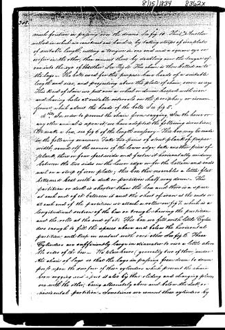
much friction in passing over the drums See fig 10. There is another method in which we construct our bands is, by taking strips of iron plate of suitable length, cutting a tongue in one end and a square eye or orifice in the other, then connect them by doubling over the tongue of one into the eye of the other See Fig 11. This chain is then bolted on to the lags. The bolts used for this purpose have heads of a suitable length and size, and projecting above the plate of chain, serve as cogs. This kind of chain we put over a wheel or drum hooped with iron and having holes at suitable intervals on the periphery or circumference, which admit the heads of the bolts See fig 8.
4th. In order to prevent the chain from sagging, when the horse or any other animal is upon it, we have adopted the following invention. We make a box, see fig 6 of the length necessary. This box may be made in the following manner. Take two pieces of stout plank of proper width, round off the corners of the lower edge, take another piece of plank, three or four feet wide and fasten it horizontally midway between the two sides on the lower edge or for the bottom and ends nail on a strip of iron plate; this box then resembles a little flat-bottomed boat with a deck or partition half way down. This partition or deck is shorter than the box and there is a space at each end of it between it and the sheet of iron at the ends or at each end of the partition we attach a roller see fig 7. which is a longitudinal section of the box or trough showing the partition and the rolls at the end of it. This box we fill with little Cylinders enough to fill the spaces above and below the horizontal partition, and keep in contact with each other See fig 6. These Cylinders are sufficiently large in diameter to rise a little above the sides of the box. The plain boxes (generally two of them) under the chain of lags so that the lags in passing from drum to drum pass upon the surface of these cylinders which prevent the chain from sagging and assist it also by their sliding and changing places one with the other, being alternately above and below the deck or horizontal partition. Sometimes we connect these cylinders by
Page 4.
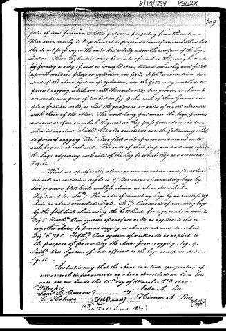
pieces of iron fastened to little guidecons projecting from the centres—These serve merely to keep them at a proper distance from each other, but they do not press any on the axles but wholly upon the surface of the Cylinders—These Cylinders may be made of wood or they may be made by forming a ring of cast or wrought iron, turned smoothly and filled up with wooden plugs or cylinders, see fig 8. Fifthly we sometimes instead of the above system of cylinders, use the following method to prevent sagging which we call the rack rolls; two grooves or channels are made in a piece of timber see fig. 9 In each of these grooves we place friction rolls, so that the guidecons or axles of one set alternate with those of the other. This rack being put under the lags, presents an even surface on which they rest as they pass from drum to drum when in motion—Sixthly We also sometimes use the following method to prevent sagging Viz: Two flat rods of iron are screwed on to each lag one at each end—The ends of these pass over and rest upon the lags adjoining each side of the lag to which they are screwed Fig. 11.
What we specifically claim as our invention and for what we ask an exclusive right is 1) Our mode of connecting lags by two or more flat link endless chains as above described. Fig. 1. and 4. See 2) The mode of connecting lags by an endless cog chain as above described Fig 3. 3rd) Our mode of connecting lags by the flat link chain using the bolt heads for cogs, as above described Fig. 5 Fourth? Our system of surface rolls as applied to this or any other chain to prevent sagging, as above made and described Fig. 6. 7 8. Fifth? Our system of rack rolls as applied to the purpose of preventing the chain from sagging Fig. 9. Sixth? Our System of rods applied to the lags as represented in Fig. 11.
In testifying that the above is a true specification of our several improvements as aforesaid we have hereunto set our hands this 18th day of March A.D 1834
Witnesses
Saml. B. Benson
F. Holmes
John A. Ellis
William A. Ellis
[Patented 11. June 1834]
Published accounts: journal notice
Notice in the monthly list of patents, with remarks
Journal of the Franklin Institute, new ser., vol. 15 (1835), p. 193 · View the page
28. For a Horse Power; John A. Pitts, and Hiram A. Pitts, the former of Brinthrop, Kennebeck county, the latter of Livermore, Oxford county, Maine, August 15.
Remarks. The improvement in the horse power claimed by the patentees, they denominate an "Endless chain and cog band." VOL. XV. No. 3.- MARCH, 1835, 25 In the specification of this patent, various modes are proposed of forming the endless bands, or chains, to sustain the wooden slats upon which the horses are to walk. There are also several modes suggested for taking off the friction of the movable floor, and also for preventing its swagging. In the first case, the patentees say, "We make two chains, similar to the flat chains used in common carding machines, only larger. The square or open link may be made of round rod iron, of any convenient size, according to the strength needed. Upon the flat links we fasten, by bolts or otherwise, logs, or slats of wood, of such thickness, length, and breadth, as will make the band of the required size. The two ends of this band being connected, the band then passes over two cog wheels, or drums, and thus the machine is ready to receive the horse." As we have already remarked, two or three other modes of forming the chain are proposed; but some of them are, like the preceding, perfectly similar to such as have been previously adopted. One of the methods of sustaining the revolving floor, and preventing its friction, is the forming an endless band of friction rollers, which run upon, and under, ways, in a manner that has been proposed and practised in other structures. All the different methods described, are distinctly and separately claimed.
DATAMP: illustration
Illustrations from DATAMP
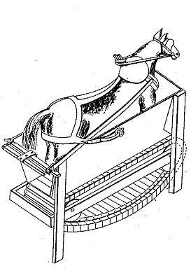

DATAMP (Directory of American Tool and Machinery Patents), via the Internet Archive · Archived DATAMP page
About this record
- Patentee
- DATAMP
- Date
- the Name and Date index of patents, DATAMP, USPTO records
- Invention
- DATAMP
- Listed in
- the Name and Date index of patents, DATAMP, USPTO records, Jim Shaw's X-patent list, the Journal of the Franklin Institute, Burke's List of Patents (1847)
- Burke's 1847 Patent Office list gives the same patent.