

Drawings and documents
National Archives restored drawings: drawing
Isaac Gallop's Patent Drawing for a Thrasher

National Archives, Restored Patent Drawings (Record Group 241) · Full-size scan at the National Archives · Catalog record
Show the text on the drawing Hide (62 words)
Words on the drawing as machine-read by the National Archives; not checked. Useful mainly for searching.
I'l / mered / 130. THRASHING. / 130. / Thrashing Machines. / [159]' / A. Cylinder Machines. / ISAAC GALLOP. / $252 / 10g / Thrasher / Patented August. 18.1834 / Ni3 / N°1 / of lazge when / CLASSIFICATION / 8364-X / Fig II / DIV ISION. / Side / N:1 / N°3 / ground plan / No2 / Tig I. / N'4 / ground Plan / Tear. / 817 / EN / oN / you / Side of large wheet / side
USPTO scan
The patent as scanned by the USPTO
-
 Page 1
-
 Page 2
-
 Page 3
-
 Page 4
-
 Page 5


U.S. Patent and Trademark Office · Google Patents
Show the transcription Hide (1,489 words)
Machine transcription (LightOnOCR) of the pages as scanned by the USPTO, most of them the handwritten copies made when the records were restored after the 1836 fire. Not checked; it can misread handwriting, so compare it with the scan.
Page 1.
8364X
I. Gallon.
Thrushing Mach.
Patented Aug. 18, 1834.
Fig. 1
Fig. 2
Fig. 1
Fig. 2
Page 2.
Aug. 18, 1834
Isaac Gallop of Plainfield Connecticut
Letters Patent
The Schedule referred to in these Letters Patent and making part of the same containing a description in the words of the said Isaac Gallop, himself of his improvement in thrashing all kinds of grain, and grass seeds by machinery at one operation called the New Thrasher.
To all persons to whom these presents shall come, Isaac Gallop of Plainfield in the County of Windham and State of Connecticut, a Citizen of the United States, gentleman, sends Greeting. Be it known that I the said Isaac Gallop, have invented, constructed, made, and applied to use, a new and useful improvement in thrashing all kinds of grain and grass seeds by machinery called the New Thrasher. Specified in the words following, viz,
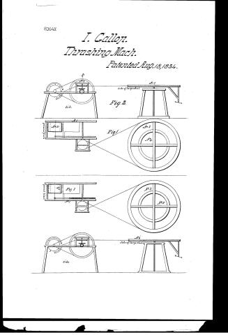
A frame is constructed of timber four inches square. The side pieces of which are eight feet long, and the end pieces 3 feet long, making the frame when completed, 8 feet by 3 feet, to be supported by timbers of the same size framed with tenons and mortises under side the frame 3 feet long, so that the top of the frame may stand horizontally about 3 feet above the surface of the floor upon which the same is to be operated. The machine is to run in this frame the exterior of which has been described as above. The size of the timber of which this frame is made, as also the dimensions of the frame, may be varied to suit the maker either in the length, breadth, or height, and the same may be constructed of iron instead of wood. See Fig 1 No 1, on the accompanying drawing.
A cylinder 30 inches diameter and 20 inches long constructed of wood in the usual mode of constructing drums or card cylinders, having an iron axle running through the centre 1 1/2 inch square, resting upon and running in guides upon the top of the frame, and as near one end of it.
Page 3.
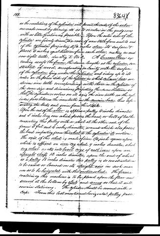
as the revolutions of the cylinder will permit, the ends of the arbor are made round by turning, so as to revolve in the guides with as little friction as possible. Upon the outer side of the cylinder are firmly driven six rows of iron teeth from end to end of the cylinder projecting 2 1/2 inches above its surface & placed 3 inches equal distance from each other, making in each row eight teeth, see Fig I No 2. A Concave Base extending across the frame, the same length as the cylinder, constructed of wood, corresponding in cavity with the surface of the cylinder, lying under the cylinder and rising up to its centre on the power side of the cylinder in which concave base are driven iron teeth corresponding with those in the cylinder of the same size and dimensions, projecting the same distance so that the cylinder revolves on its axis the iron teeth on the cylinder pass between the iron teeth in the concave base, thus separating the seeds and grain from the stock.
Upon the end of the arbor is applied a pulley 6 inches diameter and 5 inches long, over which passes the band, or belt of leather connecting this pulley with a wheel at the other end of the frame 5 feet and 6 inches diameter, around which also passes the band imparting from this wheel to the cylinder its motion. The axis of this wheel is made of iron 1 1/2 inch square upon which is affixed an iron cog wheel 4 inches diameter, which cog wheel works into bevel cogs of cast iron upon an upright shaft 12 inches diameter, upon the end of which is a pulley 18 inches diameter this pulley is so constructed as to be raised or lowered on its upright axis in such manner as to be horizontal with the motion wheel. The frame containing this machine is to be placed upon the floor and secured at the bottom by cleats and screws so that it will remain stationary. The cylinder should be covered with a cap. From this last mentioned horizontal pulley pass
Page 4.
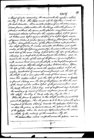
a Band of rope connecting the same with the motion wheel see Fig I No 3. This Rope must not be less than 1 inch or 1 1/4 inch diameter. At a suitable distance from the above mentioned frame, either within the building where the frame is placed, or without the same, as the operator may find most convenient stands a frame for the motion wheel 6 feet square at bottom and 8 feet square at top, 5 or 6 feet high, made of square timber 4 inches square standing flat upon the ground or floor. Through the centre of this frame stands a perpendicular shaft of timber 8 inches diameter at bottom and eight inches at the top decreasing gradually, banded with iron at top, each side of the arms being 2 feet above the top of the frame, standing in a cross sill in the centre at the bottom, and secured in the centre of the top of the frame, by one cross piece with an iron band around the shaft, or two cross pieces of wood halved out so that this shaft revolves between them. Upon the top of this shaft is made the motion wheel 11 feet diameter, constructed by means of arms framed into the top of the shaft with a rim upon the ends of these arms, and between this motion wheel and the top of its frame a sweep is framed sloping over the top of the frame, so that the end of the sweep reaches within 3 feet of the ground or floor, and the sweep should be 7 feet long, and of sufficient size to propel the machinery by means of horse or ox power from the end of this shaft see Fig I No 4, also see Fig II, No 1.
When the power is applied to this shaft, motion immediately given to the cylinder, then the grain is to be laid upon the apron composed of boards, sloping towards the cylinder 3 feet long so that the grain is passed down the apron to the teeth of the cylinder where the seeds are separated from the straw or stalks by the velocity of the machine Fig III.
The concave Bees extends one fourth around the cylinder and no
Page 5.
more, rising to the centre of the arbor of the cylinder, and sinking from thence one quarter of its diameter, see Fig III. To support the upright shaft F, II. No 2, there is to be raised upon the top of the frame, by timbers the same size as the frame itself, framed into the top piece, extending horizontally 1 1/2 feet, then two pieces perpendicular framed into them rising 3 feet perpendicular with a cap piece 3 feet long, so as to let the upright shaft turn in the lower side of this cap piece, and the 18 inch pulley revolves between these upright timbers, a crease or groove to be cut into a point on the edge of the pulleys so as to receive and hold down the rope from the motion wheel, see Fig II No 3. The drawing hereto annexed is made part of this schedule, and unto that reference is to be had.
If the frame for the motion wheel is not sufficiently heavy to preserve its distance from the machine (so that the hair may pass between them) then the bottom of the frame for the motion wheel should be loaded with stone.
The foregoing invention does not embrace, and the petition does not claim that the cylinder of itself, the pulley, the arbor, or the motion wheel or either of them, when disconnected, are of his invention but the petition in his application for his Patent does claim as new, useful and of his own invention the peculiar structure and position of the conical base, and its relative proportion to the cylinder, the arrangement of the teeth in the same and their relative peculiar contact with those on the cylinder, the position and effect of the bevel cogs and the relative size and proportion of the several wheels and pulleys, cog wheels to and with the motion wheel, and the cylinder together with their combination, are all new and useful in their results and are a discovery of his own, and belong to no one else, and for these improvements and discoveries this patent is claimed and is to be known and designated by the name aforesaid, viz: The New Thrasher.
In testimony that the above is a true specification of my said improvement, as above described, I have hereto set my hand this 12th day of June Anno Domini 1834.
Giac Gallop
Exd. Witness
Wm Andrew J. Jackson
Richard Fenner
(Patented 16th August 1834) (1612 words)
(Drawing)
Published accounts: journal notice
Notice in the monthly list of patents, with remarks
Journal of the Franklin Institute, new ser., vol. 15 (1835), p. 195 · View the page
34. For a Thrashing Machine; Isaac Gallop, Plainfield, Windham county, Connecticut, August 18.
Remarks. This machine is nominally new, but substantially old. It is called the "New Thrasher," but consists of a cylinder set with teeth, and a concave similarly furnished, so much like others previously in use, that they might very well be confounded together. The patentee, however, seems to think otherwise, for he claims as new and useful, and of his own invention, the peculiar structure and position of the concave base, and its relative proportion to the cylinder; the arrangement of the teeth on the same, and their peculiar contact with those on the cylinder. The position and effect of the bevil cogs, and the relative size and proportion of the several wheels, pulleys, cog wheels, to and with the motion wheels, and the cylinder, together with their combinations, are all new and useful in their results, and are a discovery of his own, and belong to no one else, and for these improvements and discoveries, this patent is claimed, and is to be known and designated by the name aforesaid, viz: "THE NEW THRASHER." Should it be thought proper to add a winnowing, to this thrashing machine, we advise that great care be taken not to pass this claim through it, lest it disappear altogether.
About this record
- Patentee
- DATAMP
- Date
- the Name and Date index of patents, DATAMP, USPTO records
- Invention
- DATAMP
- Listed in
- the Name and Date index of patents, DATAMP, USPTO records, Jim Shaw's X-patent list, the Journal of the Franklin Institute, Burke's List of Patents (1847)
- Burke's 1847 Patent Office list gives the same patent.