

Drawings and documents
National Archives restored drawings: drawing
D. Treadwell's Patent Drawing for a Combing Machine for Hemp, Flax, and Wool

National Archives, Restored Patent Drawings (Record Group 241) · Full-size scan at the National Archives · Catalog record
Show the text on the drawing Hide (102 words)
Words on the drawing as machine-read by the National Archives; not checked. Useful mainly for searching.
NONTION / 9366-X / DJ ISION. / Combing / nn Flax and Wool / 13 / to 289 / La / Patented Aug. 18,1834 / HL / Fig.1 / Px / ДДД / 13. BRAKES & GINS. / Hackling Machines. / TC / "ho,model" / D, Treadwell Haskling machine / R.R are clearers, which are / Pating 18, 1834 / our of place by the endless leather beets S.S ing thent / clearers on arriving as inclines I ,are by them raised thus forcing feat out of I, I / Fig.2. 2. / till's acted on by teeth cof cylinderB / D. / II / T' / IC / M. / F1G, / CA / Scale of Feet
USPTO scan
The patent as scanned by the USPTO
-
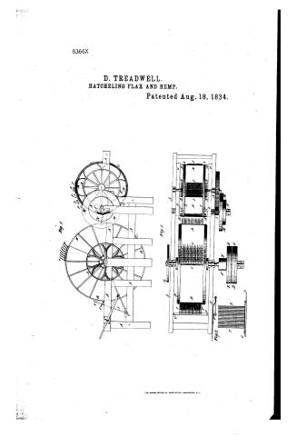 Page 1
-
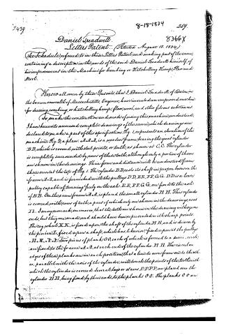 Page 2
-
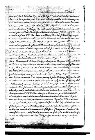 Page 3
-
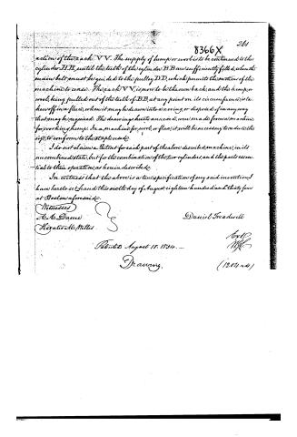 Page 4


U.S. Patent and Trademark Office · Google Patents
Show the transcription Hide (1,235 words)
Machine transcription (LightOnOCR) of the pages as scanned by the USPTO, most of them the handwritten copies made when the records were restored after the 1836 fire. Not checked; it can misread handwriting, so compare it with the scan.
Page 1.
8366X
D. TREADWELL.
HATCHELING FLAX AND HEMP.
Patented Aug. 18, 1834.

THE NORRIS PETERS CO., PHOTO-LITHO., WASHINGTON, D. C.
Page 2.
2439
8-18-1834 259.
Daniel Spadwell. 8366X
Letters Patent. (Patented August 18, 1834.)
(The Schedule) referred to in these Letters Patent, and making part of the same, containing a description in the words of the said Daniel Spadwell himself, of his improvement in the Machine for combing or Hatchelling Hemp, Flax, and Wool.
Know all men by these Presents, that I, Daniel Spadwell, of Boston, in the commonwealth of Massachusetts, Engineer, have invented an improved machine for dressing, combing, or hatchelling hemp, flax, wool, and other fibrous substances.
To make the construction and mode of using this machine understood, I have hereto annexed complete drawings of the same, which drawings are declared to make a part of this specification. Fig. 1, represents an elevation of the machine; Fig. 2, a plan. A A A, is a wooden frame, bearing the great cylinder B B, which is covered with steel points, or teeth, as shown at C C. The cylinder is completely surrounded by rows of these teeth, although only a portion of them are shown in the drawings. Their form and distance will be understood from those seen at the top of Fig. 1. The cylinder B B rests its shaft in proper boxes on the frame A A, and is furnished with the pulleys D D, E E, F F, G G. D D is a loose pulley capable of turning freely on the axle. E E, F F, G G, are fixed to the axle of B B. On the same frame A A, is placed the small cylinder H H. This cylinder is covered with rows of teeth, a part of which only are shown in the drawings, as at I I. I may remark, moreover, that the teeth are shown in the drawing with square ends, but they are made and should have been represented with sharp points. The cog wheel K K, is fixed upon the shaft of the cylinder H H, and is driven by the pinion L, fixed upon a shaft, which has, likewise, fixed upon it the pulleys M M, N N. Two pieces of plank O O, each of which is formed to a semi-circle, are fixed to the frame A A, at each end of the cylinder H H. The circular edges of these planks are in such position, that a line drawn from one to the other, parallel with the axis of the cylinder, will touch the points of the teeth with which the cylinder is covered. Several slats or staves P P P, are placed over the cylinder H H, being fixed by their ends, to the planks O O. The planks O O are
Page 3.
shown at Fig. 2, but not at Fig. 1, and the laps P P are shown at Fig. 1, and not at Fig. 2. R R R represent rods or cleaves, which are placed, one between every row of teeth with which the cylinder is surrounded. These cleaves are kept from falling out of their places, by two belts of leather S S, which surround them, and are secured to them by thongs. The ends of the cleaves R R project beyond the ends of cylinder H H. There is fixed to the inside of each of the planks O O, a wedge or inclined plane T T. The shape or outline of the sides of these wedges may be traced in the dotted line at Fig. 1, and their connection with the other parts is seen at Fig. 2. It will thus be seen that the cleaves R R, as they pass over these wedges, are forced away from the cylinder H H, towards the cylinder B B, so as to approach very near to the teeth of that cylinder. A shaft V, is placed across the frame A A, where it rests in proper boxes. This shaft is commanded by an arm, to which a weight may be attached, and handled, as seen in the drawings, and has, moreover, fixed to it, the racks V V, seen separately, and in another view, at Fig. 3. The bars of which the rack is formed, lay into the spaces between the teeth on the large cylinder. An open belt must be passed round the pulley F, and the pulley H, or if the cylinder H, should be required to move with greater speed, then the belt should pass round the pulleys F and A. The machine is driven by a belt passing from any proper drum, and round the pulley E E. To put the machine in operation, it is only necessary to pass the hemp, flax, wool, or other substance to be operated upon to the cylinder H, by means of a feeding cloth or table, properly arranged for the purpose. The large cylinder being put in motion in the direction of the arrow, the small cylinder, from its connection with it, by the belt pulleys and gear heretofore described, passes with the hemp or wool upon it, under the large or flaves P P P P. These flaves press the hemp or wool into the teeth T T. When the four or five ends of the material thus carried in the teeth arrive at the point nearest to the large cylinder, the cleaves R R, rising on the wedges T T, raise those ends out of the teeth T T, and they are struck by the teeth C C, by which the operation of clearing, combing or hatchelling, is performed. The cylinders continuing to move in this way, when the hindmost ends of the fibres of hemp or wool, arrive at the place of the wedge T T, the fibres slip from the teeth of the cylinder H, into those of B, and are carried round with them, being pressed down upon the cylinder by the
Page 4.
action of the rack VV. The supply of hemp or wool is to be continued to the cylinder HH, until the teeth of the cylinder BB are sufficiently filled, when the main belt must be guided to the pulley DD, which permits the motion of the machine to cease. The rack VV, is now to be thrown back, and the hemp, or wool, being pulled out of the teeth of BB, at any point on its circumference, is taken off in a fleece, when it may be drawn into a roving, or disposed of in any way that may be required. The drawings hereto annexed, were made from a machine for working hemp. In a machine for wool, or flax, it will be necessary to reduce the size, to conform to the staple used.
I do not claim a Patent for each part of the above described machine, in its uncombined state, but for the combination of the two cylinders, and the parts essential to their operation, as herein described.
In witness that the above is a true specification of my said invention, I have hereunto set hand this sixth day of August, eighteen hundred and thirty-four at Boston aforesaid.
Witnesses
A. A. Dame
Horatio A. Millis
Daniel Freadwell
Patented August 18, 1834.
Drawing.
Published accounts: journal notice
Notice in the monthly list of patents, with remarks
Journal of the Franklin Institute, new ser., vol. 15 (1835), p. 194 · View the page
31. For a machine for Hatchelling Hemp, Flax, and Wool; Daniel Treadwell, Boston, Massachusetts, August 18.
Remarks. The specification of this patent refers throughout to the drawings, and we do not think that without them the construction of the machine could be understood; we shall not, therefore, attempt to describe it.
About this record
- Patentee
- DATAMP
- Date
- the Name and Date index of patents, DATAMP, USPTO records
- Invention
- DATAMP
- Listed in
- the Name and Date index of patents, DATAMP, USPTO records, Jim Shaw's X-patent list, the Journal of the Franklin Institute, Burke's List of Patents (1847)
- Burke's 1847 Patent Office list gives the same patent.