

Drawings and documents
National Archives restored drawings: drawing
Otis Tuft's Patent Drawing for a Power Printing Press


National Archives, Restored Patent Drawings (Record Group 241) · Full-size scan at the National Archives · Catalog record
Show the text on the drawing Hide (156 words)
Words on the drawing as machine-read by the National Archives; not checked. Useful mainly for searching.
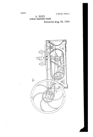
Sheet 1. $13- / Bed & Pleton / - Roller ink / #8380X / CLASSIFICATION / OTIS TUFTS / 8380X / DIVISION. / Power Printino Prefs / Patented 22nd Aug: 1834. / Fig.S. Side Elevation / 722 / (0 0) / Bo / ID / E' / on / Ois / 72 / 71 / CoRS.Dol
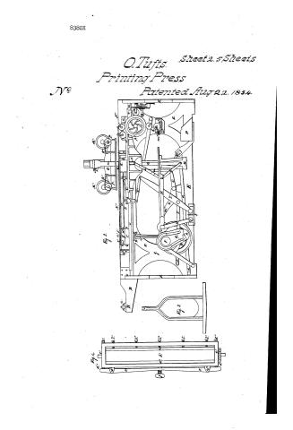
Sheet 2. CLASSIFICATION / 7380X / DIV ISION. / Fid.2. Longitudinal Section. / И" / c" / of" / UTP / VP / 13 / 4. / of / 2" / T' / 12" / On) / a" / 3" / ??" / INbo / Oq / H. / Ps / Fig / k. / 32" / of" / 02" / 1" / of
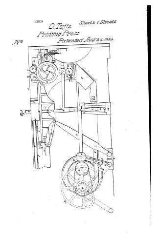
Sheet 3. CLASSIFICATION / 8380 X / / DIVISION. / и" / u" / 70 / T' / b" / 110 / a" / C" / F' / I, / 11 / O/
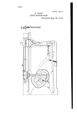
Sheet 4. Bromer / CLASSIFICATION / 8380 X / 2 alternatey frisket, imployed / DIVISION. / a' / Fig.6 / Figy / g'org / yo / c' / s' / p' / pl / 2" / "A / n' / Om / 01
Sheet 5. CLASSIFICATION / 8380X / 'NOISIAIC / Plan. / Fig. / 11. / zcl / w" / E' / of / IT / IT / 11 / R" / T' / I' / P) / rig / R" / R" / T2 / W" / of / of / Fig.10. / e" / al / 00 / 72 / Fig / 8.
USPTO scan
The patent as scanned by the USPTO
-
 Page 1
-
 Page 2
-
 Page 3
-
 Page 4
-
 Page 5
-
 Page 6
-
 Page 7
-
 Page 8
-
 Page 9
-
 Page 10
-
 Page 11
-
 Page 12
-
 Page 13
-
 Page 14
-
 Page 15
-
 Page 16
-
 Page 17
-
 Page 18
-
 Page 19


U.S. Patent and Trademark Office · Google Patents
Show the transcription Hide (5,455 words)
Machine transcription (LightOnOCR) of the pages as scanned by the USPTO, most of them the handwritten copies made when the records were restored after the 1836 fire. Not checked; it can misread handwriting, so compare it with the scan.
Page 1.
8380X
5 Sheets—Sheet 1.
O. TUFT.
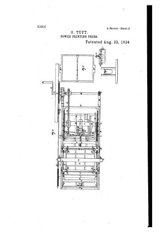
POWER PRINTING PRESS.
Patented Aug. 22, 1834.
Fig. 1.
Page 2.
8380X
O. Tufts. Sheet 2.5 Sheets
Printing Press
No. Patented Aug 22. 1834.

Page 3.
8380X
O. Tufts. Sheet 3. 5 Sheets.
Printing Press.
Patented Aug. 22, 1834.
No.
Fig. 5.
Page 4.
8380X
5 Sheets—Sheet 4.
O. TUFT.
POWER PRINTING PRESS.
Patented Aug. 22, 1834.

Page 5.
8380X
5 Sheets—Sheet 5.
O. TUFT.
POWER PRINTING PRESS.
Patented Aug. 22, 1834

Page 6.
Aug 22 1834 34
Otis Tufts
Letters Patent
The schedule referred to in these Letters Patent and making part of the same containing a description in the words of the said Otis Tufts himself of his improvements in the Power Printing Press.
To all persons to whom these presents shall come Otis Tufts of Boston in the County of Suffolk and state of Massachusetts do give greeting. Be it known that I the said Otis Tufts have invented made and applied to use certain improvements of machinery for the purposes of printing paper or other substances generally used for receiving impressions from types. Which inventions when all combined together with other parts constitute and are commonly known by the application of a "Power Printing Press". The disposition arrangement and use of the several parts shall be described and set forth in the following words and annexed drawings which taken in connection form my specification. The main or principle difference between this Power Press and others now in use consists in supplying it with paper to be printed from one side of the forme by using two feeders one of which is under the operation of an impression from the platen while the sheet of paper last printed is being removed from the second feeder and another sheet supplied. As soon as the first feeder mentioned has received an impression from the types it is withdrawn by the operation of the machinery from between the platen and forme and the second feeder caused to pass in between the platen and forme in time to be acted on in its turn. So as in succession each passes out from between the platen and forme with its printed sheet while the other with the sheet to be printed is made to pass in between the platen and forme and represents the flywheel of the press constructed in the usual form and suitable size being attached to the driving shaft. The shaft is operated on and caused to turn round by means of a
Drawing 1. Fig. 1.
Page 7.
not labor expended on a crank c, or by means of a steam engine, horse or water power, acting on a drum or pulley affixed in its end. The shaft D revolves at one end in a composition or other suitable metal box or attached to the extremity of the strut D, of the cast iron frame D, D. The opposite end rests on the periphery of a friction wheel b, in the strut D, and a pinion c is fastened in the driving shaft B, whose teeth act in the interstices or links of a chain belt d, passing around it and the cogged wheel c, in the main shaft B. The frame D, D, of the press is of cast iron but may be constructed of wood or other suitable material shaped and formed as seen in the drawings or otherwise shaped and formed to answer the intended purposes of supporting the bed platen and machinery for the operations connected with the same. The main shaft B has journals at each extremity, revolving in composition or other suitable metal boxes S, S, attached to the upright posts S, S, of the frame work D, D, as seen and represented in the drawings. To the centre of the main shaft B is secured in a proper manner a cam C, construction of the form seen in Figs 2, 3, having a roller h, in its small end for the purpose of diminishing the friction at the time of the impression and which also turns round a certain distance at every revolution of the cam, thus presenting a new surface for the roll in the end of the platen to move over by which the abrasion of the rolls is greatly diminished. The opposite end of the cam, the arc of a circle, the centre being in the centre of the shaft. During the revolution of the last mentioned part on or against the roller i in the end of the platen B, it produces no motion of the platen either backward or forward but as soon as the side of the cam comes in contact with the roll it pushes it forward until it arrives at the extreme end of the roll on the cam when the impression ceases, and the opposite side of the cam permits the platen to reverse until the roll in the end of the platen meets the greater surface of the opposite arc of
Page 8.
of the cam and again becomes stationary during the revolution of the said surface. The piston H is supported during its back and forth movements by the upright vibrator Scf of the form seen in Fig. 8, to which it is attached at the top by a joint. The lower end of this upright Sc revolves on bearings L, L, attached to a bar or connecting piece of iron L, of the opposite sides of the frame L, L. The opposite end of the piston H rests on the centre pin of the toggle joints K, K, and causes them to be brought together or in a straight line with each other by the centre pin bearing against the side of a vertical space cast in the lower side of the piston as more clearly represented in Fig. 3. That part of the piston from where it rests on the centre pin of the toggles (when in action) to the extreme end of the same is formed flat on the lower side, so that when the piston is raised this part offers no projections but a plain surface throughout its length to the centre pin of the toggles moves over the said centre pin without producing any back or forth motion of the joints.
The lower end of the toggle K rests on a pin or stop in the large iron roof beam M. The upper end of the toggle K plays on a similar pin or stop in the lower side of the bed N. The platen O has a large iron beam P, cast or attached to its upper side, the ends R, R, projecting over the sides of the frame L, L. Strong wrought iron bolts Q, having keys and nuts at their tops to admit of their being screwed to the projecting ends of the roof beam of the platen, pass across and through guide keys in a vertical direction and are screwed by heads at their opposite ends to the roof beam M. The platen O and beam M, and connecting bolts Q, are balanced by a counterpoise weight R attached to a lever formed of projections from a horizontal shaft P, supported at its ends by journals and keys attached to the opposite sides of the frame L, L; the shaft running in the fulcrums of the lever. On the extremity of the horizontal
Page 9.
Horizontal shaft pa is fixed a curve projecting iron q, whose end is hollowed out as a step to secure and support a small pitman r. The upper end of the small pitman r terminates in a small ball which turns in a hemispherical socket in the lower side of the head of the upright-bolt o. The fly wheel being set in motion turns the driving shaft B, thereby causing the cogged pinion e to turn round by the intervention of the chain belt, the cogged wheel e, in the main shaft E. The cam C, revolving with the shaft, acts in the pitman which it pushes forward communicating the motion to the toggles, bringing them in a straight line at the same time drawing downwards the platen on the sheet between it and the forme of type, thus giving the impression. On the main shaft B is fixed the groove cam R, for the purpose of operating on the friskets to produce their rectilinear motion in and out from between the platen and forme. After the impression has taken place the toggles are brought back as the platen rises by a cam S on the main shaft (of the form seen in the drawing or otherwise shaped and formed to answer the purpose) as the shaft revolves this cam presses down an arm or stud B" attached to the upright E. The principal object of this cam is to always endure the back motion of the toggles, which as they are brought in a straight line with each other are sometimes liable in printing presses to remain so and not depart from it. A small iron or steel roller traversing on a pin in the end of the bent bar S, travels in the groove of the cam R. The bar S, at its other extreme by, is attached to the upright vibrator T, by a pin at a sufficient distance from its foot or centre of motion, so as to form a joint to admit the movements to and fro of the vibrator. The vibrator S is formed as represented in Fig. 3, open on the centre to permit the passage through and action of the pitman and upright E. At its foot it moves on swivel bearings.
Page 10.
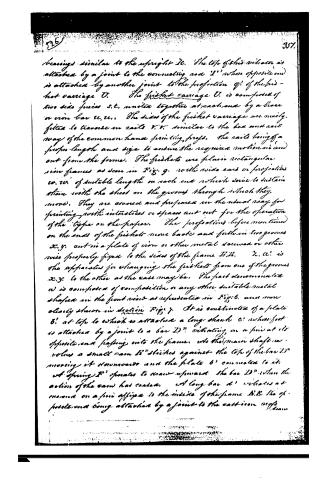
bearings similar to the upright Ic. The top of this vibrator is attached by a joint to the connecting rod L' whose opposite end is attached by another joint to the projection q' of the first carriage U. The first carriage U is composed of two side pieces s, t, united together at each end by a brace or iron bar u, u. The sides of the first carriage are merely fitted to traverse on rails v, v, similar to the bed and rail way of the common hand printing press. The rails being of a proper length and size to endure the required motion in and out from the forms. The firsts are plain rectangular iron frames as seen in Fig. 9, with wide ears or projections w, w, of suitable length on each end which serve to sustain them with the sheet in the grooves through which they move. They are covered and prepared in the usual way for printing, with indentures or spaces cut out for the operation of the type on the paper. The projections before mentioned on the ends of the firsts move back and forth in two grooves x, y, cut in a plate of iron or other metal screwed or otherwise properly fixed to the sides of the frame H, H. Z, a, is the apparatus for changing the firsts from one of the grooves x, y, to the other as the case may be. The part denominated a is composed of composition or any other suitable metal shaped in the front view as represented in Fig. 6, and more clearly shown in section Fig. 7. It is constituted of a plate b' at the top to which is attached a long shaft c' whose foot is attached by a joint to a bar D" vibrating on a pin at its opposite end passing into the frame, into the main shaft revolves a small cam b" strikes against the top of the bar D" moving it downward and the plate b' connected to it. A spring F' operates to draw upward the bar D" when the action of the cam has ceased. A long bar d' vibrates at one end on a pin affixed to the inside of the frame H, H, the opposite end being attached by a joint to the cast iron rods
Page 11.
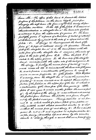
beam AB. The office of this bar is to prevent the lateral pressure of the pitman on the lower toggle joint from changing the roof beam AB from a right line during its perpendicular motions. To the top of the plate B' is screwed or otherwise attached a straight bar c', the lower side of which is intended to form the upper side of a groove E'. The lower part of the groove E' is formed of a bent piece of metal g' attached at its lower end by a joint to the side of a space cut in the plate B'. A spring h' bears against the back of the piece g' to press it outward during its operations. The outer face of the straight bar c' is in the same plane with the outer face of another straight bar i' screwed or otherwise affixed to the sides of the frame E, E. When the plate B' is raised to the upper groove X, the lower side of the straight bar c' coincides with the upper side of the said groove X. The spring h' pushing the curved piece of metal g' outward causes its top to coincide with the lower side of the groove X, so as to produce a continuation of the groove X, ready to receive an ear or projection w' of the fustlet. While the plate B' is moving down the straight bar i' causes the curved piece of metal g' to move inward so as to deposit the ear or projection of the fustlet on the upper face of the bar i' which is a continuation of the lower face of the lower groove Y. As the plate B' rises again to receive another fustlet the curved part g', by the pressure of the spring h', moves outward and receives the fustlet from between the plates and frames, brought out by the fustlet carriage. Having described a new form to Z which consists of a plain plate of composition or other suitable metal shaped somewhat similar to a but without the curved piece g' and spring h'. It has a simple groove M, cut in it and is guided in a perpendicular direction during its motions up and down by the circular guide L, sliding through a round hole in a piece of iron
Page 12.
359.
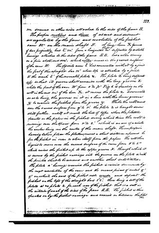
m. screws or otherwise attached to the sides of the frame E. The proper motions and times of ascent and descent are regulated by the form and revolution of the friction cam W on the main shaft E. A long lever X formed of two projecting bars C, m, from a horizontal shaft, supported by suitable bearings attached to the sides of the frame E E, has a roller turning on a fine axis, and m', which roller moves in the grooved surface of the cam W. The opposite arm C' has connected with it by a joint the foot of the upright bar m' whose top is attached by a joint to the crank C' of the movable plate X. The plate X being supported so that its groove shall coincide with the long groove X while the part of the cam W from O to P' Fig. 6 is operating on the roll in the cam m' of the bar X, it moves the plate X downwards so as to bring the groove in it in a line with the lower groove Y, to receive the frisket from the groove Y. While the roll moves over the curved surface from q' to r', the plate X is brought down still further, until it meets the bed of type when the platen operates on the paper in the frisket during which time the roll is moving over the space from r' to S, which is an arc of a circle the centre being in the centre of the main shaft. The impression having taken place the platen moves a short distance upwards to free the frisket in order to clear itself from the paper. The roll then begins to move over the curved surface of the cam from S to C" which raises the frisket up to the upper groove X, through which it is moved by the frisket carriage into the groove on the plate a with the printed sheet to be removed and another sheet substituted. The plate a having received the frisket is raised downwards by the next revolution of the cam and the curved surface of metal g, g' on which the base of the frisket rests ascends and deposits the frisket on the tops of the straight bars C C', there being a set of the plates a to plate X, for each row of the frisket that is a roll in the middle of each of the sides of the frame E E. The frisket is then operated on by the frisket carriage and comes in between the plat
Page 13.
ten and forms for an impression. That part of the fishlet carriage which produces the movements back and forth of the fishlets in the grooves x, y, is represented at t' t'. t' is an upright projecting piece of iron on the top of each side of the fishlet carriage. Its office is to push the fishlet out from between the platten and forme through the groove x, into the groove in the plate a'. a' is a small catch vibrating on and connected to the fishlet carriage by a joint at s, and always pressed upwards by a small spring v'. When the fishlet carriage passes outward from the platten with a fishlet the small catch a' strikes against the under surface of the car on the lower fishlet and is pressed down during its motion under the said surface. As soon as it leaves the surface it flies upwards. When the fishlet carriage is carried inward the ends of the catches a' a' come in contact with the cars or projections of the fishlet thus pushing it through the lower sets of grooves y, y, into the groove in the plate a' when it is received and carried downward by the cam w, to receive an impression from the platten. Afterwards it is raised by the action of the said cam w, to the upper groove x. The fishlet carriage then moving outward the projections t' t' on each of the sides of the carriage strike against the cars of the fishlet and push it through the upper grooves x into the groove in the plate a'. The above arrangement of the machinery is considered fully sufficient for the operation of the fishlet but to guard against any accident which might happen by the carves piece c' catching against and lifting the car of the fishlet during its upward movement two small pieces of iron u' u' are so tiny at an angle corner of each that the action of gravity will cause them always to stand outward to prevent the fishlet car from rising. The car during its downward motion presses the small catches u' u' into the notches or spaces in the plate of iron in which the grooves x, y, are cut as seen in Fig. 6, but as soon as the fishlet is deposited on the lower edge of the lower groove the small catches are relieved.
Page 14.
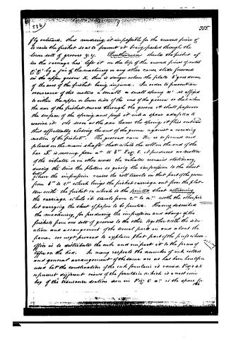
fly outward, thus rendering it impossible for the curved piece g' to raise the fustet so as to prevent it being pushed through the lower set of grooves y. y. Furthermore should the fustet of the carriage has left it on the top of the curved pieces of metal g'. g'. by a pair of the machinery or any other cause, slide forward in the upper groove x, there is danger when the plate b' goes down, if the rear of the fustet being injured. In order to prevent an occurrence of this nature a small or small spring x' is affixed to either the upper or lower side of the end of the groove so that when the rear of the fustet moves through the groove it shall pass over the surface of the spring and press it into a space adapted to receive it. As soon as the rear leaves the spring it flies outward thus effectively closing the end of the groove against a receding motion of the fustet. The groove cam N, is so formed and placed on the main shaft that while the roll on the end of the bar S, is moving from a" to b" Fig. 5, it produces no motion of the vibrator or in other words the vibrator remains stationary, during the time the platen is giving the impression to the sheet but when the impression ceases the roll travels in that part of the groove from b" to c" which brings the fustet carriage out from the platen with the fustet on which is the printed sheet returning the carriage while it travels from c" to a" with the other part carrying the sheet of paper to be printed. Having described the machinery, for producing the impression and change of the fustets from one set of grooves to the other, together with the situation and arrangement of the several parts in and about the frame, we next proceed to explain that part of the press whose office is to distribute the ink and impart it to the form of type on the bed. In many respects the manner of ink rollers and general arrangement of the same are as has been heretofore used but the construction of the ink fountain is various. Figs. 6 & 7 represent different views of the fountain which is a cast iron box of the transverse section shown in Fig. 6; a" is the space for
Page 15.
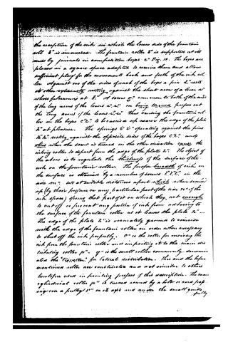
the reception of the ink in which the lower side of the fountain roller 8" is immersed. The fountain roller 8" is supported at its ends by journals in accommodation boxes c" Fig. 10. The boxes are placed in a square space adapted to receive them and allow sufficient play for the movement back and forth of the ink roller against one of the sides of each of the boxes a pin d" rests at either extremity resting against the short arm of a lever e' whose fulcrum is at f." A screw g" common to both of the ends of the long arms of the levers e', e" on being turned pushes out the long arms of the levers e', e" thus causing the fountain roller on the boxes c', c" to be carried up nearer the edge of the plate 7" at pleasure. The springs i" i" operating against the pins h" h" resting against the opposite sides of the boxes c', c" and thus when the screw is turned in the other direction cause the ink roller to depart from the edge of the plate 7". The object of the above is to regulate the thickness of the surface of the ink on the fountain roller. The proper breadth of ink on the surface is obtained by a number of screws l", l", l" in the side m" set at suitable distances apart which when screwed up (by their pressure on any particular part of the side n" of the ink space) spring that part of it on which they act enough to cut off or prevent any portion of ink from adhering to the surface of the fountain roller as it leaves the plate 7". The edge of the plate 7" is accurately ground to coincide with the edge of the fountain roller in order when necessary to shut off the ink perfectly. O" is the roller for receiving the ink from the fountain roller and imparting it to the main ink distributing roller p". q" is the small roller commonly denominated the "liquator" for lateral distribution. This and the before mentioned rollers are constructed and act similar to others hereafter used in printing presses of this description. The main cylindrical roller p" is turned round by a belt or cord passing over a pulley s" on its axis and upon the small guide pulley
Page 16.
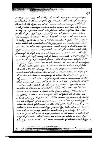
pulleys S"S" over the pulley C" on the axis of the driving shaft or attached to the arms of the fly wheel. The rollers for applying the ink to the types are R" R" and revolve in bearings attached to the further carriage which when it goes out from the forme, carrying a further with the printer sheet applies these rollers to the surface of the types passing over the forme twice, where the carriage returns it deposits the rollers on the main distributing cylinder P" — All the above parts of the inking apparatus with the exception of the forme are constant and act similar to those herefore used with only a little variation of form and size to adapt them to the particular shape of the frame of the press and machinery connected to it. M" M" are rollers for supporting the platen on rails N"N" affixed to or making a part of the frame. Two horizontal shafts O" O" revolve in boxes connected to the platen as seen in the drawings.
On the extremities of each are cranks on which are placed the rolls M"M" During the time the press is in action these cranks with the rolls are turned up in the position in Fig's 1 & 2, but when it becomes necessary to slide the platen away from the forme on the beam they may be turned downwards so that their circumferences shall touch on the tops of the rails N"N".
A circular plate P" having two notches opposite to one another is fixed on each shaft. When the rolls M"M" are turned up or down a projection from a spring R" enters into one of these notches and confines the shaft to the position in which it may be placed. What is usually termed by printers the strength of the impression is regulated by dividing the circular parts of the nuts on the tops of the bolts O O into equal distances and counterboring or drilling holes at each division into which an index pointer on the end of a spring R" enters and confines the nut to any position on the screw in which it may be placed. Both nuts are divided alike so that by turning either each the same number of divisional distances
Page 17.
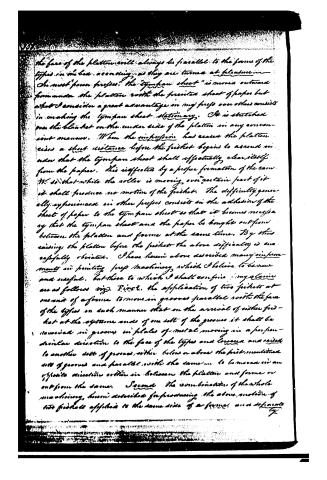
the face of the platten will always be parallel to the forms of the types in the box, according as they are turned at pleasure.
On most "power presses" the "tympan sheet" is moved outward from under the platten with the printed sheet of paper but what I consider a great advantage in my press over others consists in making the tympan sheet stationary. It is stretched over the blanket on the under side of the platten in any convenient manner. When the impression has ceased the platten rises a short distance before the frisket begins to ascend in order that the tympan sheet shall effectually clear itself from the paper. This is effected by a proper formation of the cam. It is so that while the roller is moving over certain part of it it shall produce no motion of the frisket. The difficulty generally experienced in other presses consists in the adhesion of the sheet of paper to the tympan sheet so that it becomes necessary that the tympan sheet and the paper be brought out from between the platten and forme at the same time. By thus raising the platten before the frisket the above difficulty is successfully obviated. I have herein above described many improvements in printing press machinery which I believe to be new and useful, but those to which I shall confine my claims are as follows viz. First, the application of two friskets at one end of a forme to move in grooves parallel with the face of the types in such manner that on the arrival of either frisket at the extreme ends of one set of the grooves it shall be received in grooves in plates of metal moving in a perpendicular direction to the face of the types and lowered and raised to another set of grooves, either below or above the first mentioned set of grooves and parallel with the same, to be moved in an opposite direction either in between the platten and forme or out from the same. Second, the combination of the whole machinery, herein described for producing the above motion of two friskets applied to the same side of a forme, and separate
Page 18.
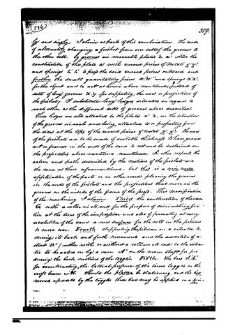
by and singly, I claim as parts of this combination: The mode of alternately changing a fishlet from one set of the grooves to the other set, by grooves in moveable plates 2, a' Also the construction of the plates as with curved pieces of metal 5', 5" and springs h', h" to push the said curved pieces outward and further the small gravitating pieces w', w" and springs x', x" for the object and to act as herein above mentioned. Instead of sets of long grooves x, y, for supporting the ears or projections of the fishlets, I substitute long ledges situated in regard to each other as the different sets of grooves above described. These ledges are also attached to the plates a' x, in the situation of the grooves in each and being attached to or projecting from the sides at the tops of the curved pieces of metal 5', 5". The ears of the fishlets are to be made of suitable thickness to have grooves cut or formed in the ends of the same to rest and be sustained on the projections above mentioned. In other respects the action and path described by the motions of the fishlets are the same as those aforementioned, but this is a mere modification of the parts or in other words placing the grooves in the ends of the fishlets and the projections that move in the grooves on the inside of the frame of the press. This modification of the machinery I claim. I'ird the construction of the cam G with a notch in its end, for the purpose of minimizing friction at the time of the impression and also of presenting at every revolution of the cam a new surface for the roll on the fishman to move over. Fourth: Supporting the fishman on a vibrator K, during its back and forth movements and the execution of a stroke B" (whether with or without a roller at end) to the vibrator, to be active only a man A" on the main shaft for producing the back motions of the luggies. Fifth: The bars d', d" for counteracting the lateral pressure of the lower luggies on the ways beam C'. Should the platen be stationary, and the hammer moved upwards by the luggies, then bars may be applied on a guide-
Page 19.
360
the manner to the bar for the same purpose of preventing the lateral pressure of the shaft toggle on the bar. Sixth: the arrangement of a vibrator T, connected by a joint to one end of a bar S, which is supported at the other end on a pin in the top of a small vibrator T', the said pin having a roller on it traveling in the grooved cam, R, on the main shaft, for producing the motion of the pusher carriage. Seventh: I claim the peculiar arrangement of the several parts for producing the impression as I have above described, together with the disposition and adaptation of the other parts of the machinery to my improvements so as to constitute what is usually denominated a "power press." In testimony that the above is a true specification of my said invention and improvements I have hereunto set my hand this nineteenth day of August in the Year of our Lord Eighteen hundred and thirty-four.
Witness:
(Left) H. Eady
Calvin Brown
Otis Sutts
(End.)
M.C.
(5316 words)
Published accounts: journal notice
Notice in the monthly list of patents, with remarks
Journal of the Franklin Institute, new ser., vol. 15 (1835), p. 202 · View the page
48. For improvements in the Power Printing Press; Otis Tufts, Boston, Massachusetts, August 22.
Remarks. We are informed in this specification, that "the principal difference between this power press and others now in use, consists in supplying it with paper to be printed from one side of the frame, by using two friskets, one of which is under the operation of an impression from the platten, while the sheet of paper last printed is being removed from the second frisket, and another sheet is applied. As soon as the frisket first mentioned has received an imprint from the types, it is withdrawn by the operation of the machinery from between the platten and form, and the second frisket caused to pass in between the platten and frame, there to be acted on in its turn. So in succession each passes out from between the platten and frame with its printed sheet, while the other with the sheet to be printed, is made to pass in between the platten and frame." After this introductory account of the general principle upon which the press operates, its whole construction is fully described, the description being made perfectly clear by the aid of drawings, of which there are five, representing the machine in plan, in elevation, and in section, in a manner so complete, that a competent workman could at once construct such a press as perfectly as though he had the original by him. These drawings were executed by Mr. R. H. Eddy, Civil Engineer, Boston. We mention this fact, as it may serve to direct patentees who wish to have this part of their application perfectly well executed. The claims are very distinctly made, but to understand them fully, would require the aid of the drawings, and should this press sustain the character which we are inclined to give to it, not from the description merely, but from having seen it, although but for a short period, in actual operation, we hope hereafter to have the means of making its construction fully known.
About this record
- Patentee
- DATAMP
- Date
- the Name and Date index of patents, DATAMP, USPTO records
- Invention
- DATAMP
- Listed in
- the Name and Date index of patents, DATAMP, USPTO records, Jim Shaw's X-patent list, the Journal of the Franklin Institute, Burke's List of Patents (1847)
- Burke's 1847 Patent Office list gives the same patent.