

Drawings and documents
National Archives restored drawings: drawing
Cyrus McGregory's Patent Drawing for a Stave Joiner

National Archives, Restored Patent Drawings (Record Group 241) · Full-size scan at the National Archives · Catalog record
Show the text on the drawing Hide (71 words)
Words on the drawing as machine-read by the National Archives; not checked. Useful mainly for searching.
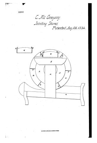
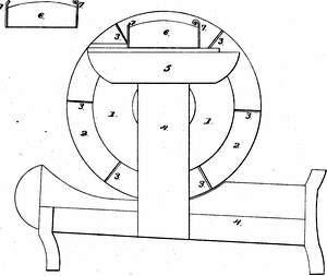
CYRUS Mc GRGORY'S / #1- / 144. WOOD WORKING. / Stave Jointer. / Haves / 3. SPECIAL WORK MACHINERY. / Patented Aug. / CLASSIFICATION [40] Jointing Staves. / 8384-7 X / DIVISION. / 70 / 77 / by / my / 2. / Fig 1 Fixed plate. Eig 2 Face of jointer wheel, - 3 Plane irons / 4 Platforme & front post. - 5 Horrizontal cap, for gàge to rest on. / 6 Gage.- - by Catch & Spring.- -
USPTO scan
The patent as scanned by the USPTO
-
 Page 1
-
 Page 2
-
 Page 3
-
 Page 4


U.S. Patent and Trademark Office · Google Patents
Show the transcription Hide (1,164 words)
Machine transcription (LightOnOCR) of the pages as scanned by the USPTO, most of them the handwritten copies made when the records were restored after the 1836 fire. Not checked; it can misread handwriting, so compare it with the scan.
Page 1.
8384X
C. Mc Gregory,
Jointing Stares,
Patented Aug. 26, 1834.

A.M. PHOTO-LITHO. CO. N.Y. (OSBORNE'S PROCESS)
Page 2.
Aug. 26, 1834
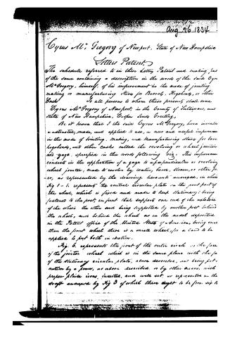
Cyrus Mc. Gregory of Newport, State of New Hampshire
Letters Patent.
The schedule referred to in these Letters Patent and making part of the same containing a description in the words of the said Cyrus Mc. Gregory, himself, of his improvement in the mode of jointing, making or manufacturing Staves for Barrels, Hogsheads, or other Casks.
To all persons to whom these presents shall come
Cyrus Mc. Gregory of Newport, in the County of Sullivan, and State of New Hampshire, Greetings.
Be it known that I the said Cyrus Mc. Gregory, have invented, constructed, made, and applied to use, a new and useful improvement in the mode of jointing, making, and manufacturing Staves for barrels, hogsheads, and other casks called the revolving or wheel jointer and gage, specified in the words following viz. This improvement consists in the application of a gage to a perpendicular or revolving wheel jointer, made to revolve by water, horse, steam, or other power, as represented by the drawing hereunto annexed, in which Fig 1-1. represents the central circular plate on the front part of the wheel, which is fixed and made to keep stationary; being fastened to the post, in front that supports one end of the axle-tree of the wheel the other end being supported by another post behind the wheel, and behind the wheel as in the model deposited in the Patent office of the United States of America, being more than the front wheel there is a small wheel, for a band to be applied to put both in motion.
Fig. 6. represents the joint of the outer circle or the face of the jointer wheel which is in the same plane with the face of the stationary circular plate, above described, and being put in motion by a power, as above described, or by other means, with proper plates iron, inserted, and well set, as represented in the draft annexed by Fig 3 of which there ought to be from six to
Page 3.
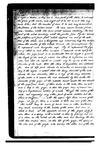
to eight or twelve, as they are in some parts of the stave, to cut across the grain of the wood, and ought not to be set so as to take any rank hole; but the number of irons to be set, may be varied at the pleasure of the builder or user. The above named circular jointer face, revolves, while the said plate remains stationary. The back parts of the wheel revolving with the jointer face Fig. 4, represent the platform and front post, which supports one end of the axle tree of the wheel, near a horizontal cup about one half the distance above the centre of the wheel through the circumference. Fig. 5, represents said horizontal cup. Fig. 6, represents the gage one of which on said plane annexed is separate at the left of the wheel. This gage must be so constructed that its length is equal to the length of the cask for which the staves to be jointed are intended, and that its depth or width, may be equal to the semi diameter of the cask, that the stave to be jointed are intended for, and its top part should be circular or crowning, according to the degree or extent that the bung diameter of the cask exceeds the end diameter, that is to say if the bung diameter of the cask is to exceed the end diameter by two inches, the diameter of the gage at the middle must exceed the end diameter of the gage one inch, if three inches in the cask, then one inch and a half in the gage, so that the gage may represent one half of a longitudinal section of a cask, through the centre of the cask not regarding any other part of said section but the plane or surface. At the upper left hand corner of the gage, at fig. 7, there is a catch to hold one end of the stave. This catch may be made of wood iron or other material any much according to the wishes of the user, but iron or steel is best, at the opposite corner of the gage at fig. 7, also there is a spring with a catch so that by placing one end of a stave in the catch at its other end, and bending the stave with that surface down on the top of the gage, the spring on the other end of the gage will receive the other end of the stave
Page 4.
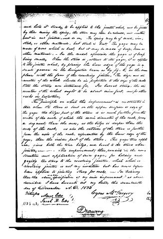
and hold it steady, to be applied to the jointer wheel, and be jointed by them moving the spring, the stone may then be released, and another bent in and jointed, and so on. The spring may be of wood, iron, steel, or other material, but steel is best. The gage may be made of wood which is best; but it may be made of brass, iron or other material. — For the model aforesaid the gage is of brass being small. When the stone is adjusted to the gage, it is applied to the jointer wheel, by placing the lower edge of the gage in a small groove in the horizontal beam as by fig. 5, in the same plane with the face of the revolving jointer. The size and diameter of the wheel should be in proportion to the size of the casks that the staves are intended for. For barrel staves, the diameter of the wheel ought to be about nine feet, and for other casks in proportion.
The principle on which this improvement is constructed is that when the stone is bent on the upper surface or edge of the gage the bidge part of the stone is as much further from the centre of the circle of which the same diameter of the cask, forms a segment, than the same, as the bidge is deeper than the edge of the cask, as also the outside of the stone is further from the axis of the cask, represented by the lower edge of the gage, than the inside part of the stone. This gage thus applied, gives both the true bidge, and level to the staves when jointed. — This improvement, then, consists in the construction and application of said gage, for holding and guiding the stave to the revolving jointer, which wheel or revolving jointer is not my invention but has never before been applied to jointing staves for casks. — In testimony that the above specification of my said improvement, as above described I have hereunto set my hand, this seventeenth day of December A.D. 1833
Witnesses:
Amos Bell
Sarah H. Bell
Gypus M. Gregory
Drawing
DATAMP: illustration
Illustrations from DATAMP

DATAMP (Directory of American Tool and Machinery Patents), via the Internet Archive · Archived DATAMP page
About this record
- Patentee
- DATAMP
- Date
- the Name and Date index of patents, DATAMP, USPTO records
- Invention
- DATAMP
- Listed in
- the Name and Date index of patents, DATAMP, USPTO records, Jim Shaw's X-patent list, Burke's List of Patents (1847)
- Burke's 1847 Patent Office list gives the same patent.