

Drawings and documents
National Archives restored drawings: drawing
John L. St. John's Patent Drawing for Reaction Water Wheels

National Archives, Restored Patent Drawings (Record Group 241) · Full-size scan at the National Archives · Catalog record
Show the text on the drawing Hide (106 words)
Words on the drawing as machine-read by the National Archives; not checked. Useful mainly for searching.
138. HYDRAULIC MOTORS / 120 / [M8] / Turbins, / & Side Direct Supply. / 5. / John L Ichn. / CLASSITICATION / 8408.x / Reaction Water-wheels. / Patented the 16th September 1834 / DIVISION. / Fight / Fig.3 / 3 Top blew of che wheel. / buckets / inches / high / ol / the / 2im / with / the / buckets. / Fig. / Tide / view / of / Fig.3 / Fig 1. Top view of the if ues. wheel 32 inches diameter / b. Hole the shaft / c the im. / Fig. 2 Side view of Fig.1. Fig. 1. 3 inohes high. / Fig.4. / Fig.2. / Patent office 11th Aug 1838. / Made under the direction of the Bonnipione of Patients / in conformity ity with act3 March 1837 / Commision of Patents
USPTO scan
The patent as scanned by the USPTO
-
 Page 1
-
 Page 2
-
 Page 3
-
 Page 4
-
 Page 5
-
 Page 6


U.S. Patent and Trademark Office · Google Patents
Show the transcription Hide (1,989 words)
Machine transcription (LightOnOCR) of the pages as scanned by the USPTO, most of them the handwritten copies made when the records were restored after the 1836 fire. Not checked; it can misread handwriting, so compare it with the scan.
Page 1.
No Printed Specification Available
8408X
J. L. St. John,
Water Wheel,
Patented Sep. 16, 1834.

Page 2.
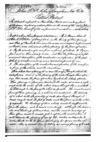
8408x Sept. 16, 1854
John L. O. John of Canajoharie, New York.
Letter Patent
The Schedule referred to in these Letters Patent and making part of the same, containing a description in the words of the said John L. O. John himself of his improvement in reaction... water wheels.
To all to whom these presents shall come. Be it known that I, John L. O. John, of Canajoharie, in the County of Montgomery and State of New York, have invented a new and useful improvement in Reaction water wheels, and wheels, operating by the power of reaction.
I. By the invention of a new form or forms of wheels. II. By improvement on those already in use — and that the following is a full and exact description, of the construction and operation of the said wheels and improvements as herein set and improved by me.
I. The description of the construction and operation of the new form or forms of the wheels and the variations.
These wheels have openings at or near the edge, through which the water passes, and it is the passing of the water through these openings that escalates the power of reaction by which the wheels operate. These openings or issues give direction to the water, at or near a right angle with the radius of the wheel drawn through them and with as little angle to the face of the wheel as possible. The number and form of these openings in a wheel is not material. The diameter of a wheel with the quantity of water discharged through it must vary to suit the fall of water and the power and the velocity required. The thickness of these wheels must be sufficient to form the issues, and be varied accordingly, although the diameter and thickness of these wheels, and the number and size of their issues must be varied, yet to explain the construction, I will describe the forming of one of 32 inches in diameter, 3 inches thick with 6 issues discharging 6 square inches of water. This is carried on by taking as many pieces of 3 inch
Page 3.
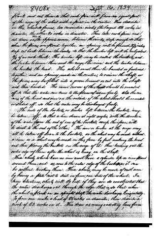
8408x Sept 16, 1834
Plank and cut them so that each piece will form an equal part of the verge of the wheel with a joint in the centre. Then describe on this wheel to form, two concentric circles, the largest 28 inches in diameter, the other 20 inches in diameter. Then take each piece and cut down on the opposite corners, between the circles, deep enough so that when the pieces are placed together, an opening will be formed 2½ inches deep cut back between the circles so that the timber left will be only about ½ of an inch thick. This timber left may be called the buckets, and the timber between them and the verge the rim, and the timber between the buckets the head. This wheel must then be banded or fastened together, and an opening made in the centre, to receive the shaft or the pieces may be fitted into a groove turned or cut into the shaft and then banded. The inner corner of the head should be rounded off so that the water can come to the place of issue freely. Also the corners of the head and rim on the outside of the wheel should be rounded or slid off, so that the water may be discharged freely.
The ends of the buckets, or timber left between the buckets, may be taken off, so that a line drawn at right angles with the direction of the water from the end of one of the buckets across the space will be direct to the end of the other. The rim or timber at the verge may all be taken off down to the buckets, or the wheel may be made without a rim, or a wheel may be made in this form by first making the head and then placing the buckets on the verge of it, then turning out the outer edge of them after the wheel is hung on the shaft.
These wheels which have no rim must have a cylinder top or rim placed around them, and as near to the outer edge of the buckets as it can be without touching them. These wheels may be made of cast iron by having a plate cast to suit in from one side of the wheel. In some situations, wheels will do best if they are so constructed that the water discharges out through the edge that is so that when the wheel is placed on an upright shaft the water discharges horizontally. To form one make a head of 28 inches in diameter, then describe a circle of 20 inches on it. Then draw as many radiating lines from
Page 4.
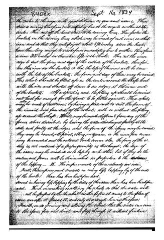
the centre to the verge with equal distances, as you want issues. Then draw a curving line from each radiating line at the verge to another at the circle. Then cut off the head down to the curving lines. Then fasten the buckets on the curving lines, which may be made of cast iron, or sheet iron and so that they will project about 5 1/2 inches above the head, have them long enough to reach from one radiating line to another, then from a rim 3 1/2 inches in diameter 1 1/2 inch thick. Then cut the inner edge to suit the form and size of the outside of the buckets. Then fasten this rim on the buckets so that the top of the rim will be even with the top of the buckets. The form and size of these may be varied. This wheel should be filled up in the centre around the shaft level with the rim and slanted off down to an edge, at the inner end of the buckets. If a spout is used, the filling up should be carried out level far enough for the spout to be filled against. These wheels may also be made of cast iron, by having a plate cast to suit the form of the inward and face side of the wheel, with or without the filling up around the shaft. Wheels may be made different from any of the forms above described, by having the water discharged partly at the side and partly at the edge, and the form of the issues may be varied. They may be round, elliptical, oblong, or square, or the inner face or cone may be rounded and the outward back cone also. The form of the issues is not material if a proper quantity is discharged, the size of the issues may be made so as to lap by each other, but if they do the motion and power will be diminished in proportion to the distance of the lapping.
II. The improvements of those already on ice.
First, this improvement consists in using less lapping by of the ends of the buckets than has been heretofore used.
Second in having less lapping by the sides of the issues than has been heretofore used.
Third in making or altering the wheels so that the water will not be forced by the wheel neither before it comes to the place of issue, nor after it passes it, and only at a single line in the face.
Fourth, in so forming and altering the wheel that the water can come to the issue, free and direct and pass through it without friction.
Page 5.
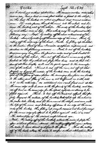
and be discharged without obstruction. The common reaction water wheels now in use, have a head or inner part which is fixed to the shaft, on this head the buckets, so called are placed and curved with a rim. The water passes through this rim into the wheel, and between the buckets, out of the wheel. The ends of the buckets, lap by each other, more or less. These wheels may be improved in the following way. First, by cutting off the inner or head ends of the buckets. Second, by cutting off the inner edge of the rim. Third, by cutting off the outer edge of the head. Fourth, by filling up the wheel in the centre. Each of these I consider as separate improvements, and are done in the following manner. — First, to cut off the buckets, draw converging lines from the point or outer end of each bucket to the centre of the wheel. Then cut off the head or inner ends of the buckets so that they shall not pass these lines, and so that the sum of all their lengths will not be quite equal to the circumference of the wheel. Second, to cut off the rim, cut off all that projects in beyond the inside of the buckets, even with the buckets, and at the place of issue follow the converging line from one bucket to the other and then if the rim is not sufficient in width, add to it in the outer edge, an additional rim can be found on it so that the inner edge will be even with the points of the buckets, and turned off true on the inner edge for the spout cylinder or staying to be fitted against. Third, to cut off the head, cut off all that projects beyond the outside of the buckets, Fourth, to fill up the wheel in the centre take blocks, and fit them round the shaft, and even with the top of the rim, and planting off, down to an edge at the inner ends of the buckets. This filling up may be carried out level far enough for the inner edge of a spout to be fitted against when it is used. The advantages of the several improvements are. First, the cutting off of the buckets allows the water to pass the space without friction. Second, the cutting off of the rim allows the water to come direct and free to the space. Third, the cutting off of the heads allows the water to escape without obstruction. Fourth.
Page 6.
8408x Sept 16, 1834
The filling up of the wheel prevents any water lying dead in the wheel and directs the water to the spine and forms a surface for the spout to be fitted against. Some wheels are so formed that one edge of the buckets is placed towards the centre of the wheel, and so that when a wheel is placed on a perpendicular shaft, the water will be discharged upward or downward. To improve these wheels, draw a line from the point or outer end of each bucket parallel with the shaft, then cut off all the heads or inner ends of the buckets, so that they shall not pass any of these lines. Then cut off all the tubs or rim that projects below or beyond the outside of the buckets and in form to suit the buckets. This allows the water to pass the space without friction, and be discharged freely. All other forms of wheels may be improved by altering them agreeable to the above principles and Rules explained. All the above forms of wheels, whether new or improved, may be used in any way, manner, or elevation that wheels, operating by the power of reaction are now used.
The parts of the above described wheels and improvements claimed original and as my invention, and for which I ask an exclusive privilege are: I. The new forms or forms of wheels as described in the first part. II. The improvements as explained, and the various improvements as described in the second part.
Witnesses
Willis, J. Powell
Baront Salisbury
John S. St. John
Drawing
(2114 Words)
(Granted 26 September 1834)
Published accounts: journal notice
Notice in the monthly list of patents, with remarks
Journal of the Franklin Institute, new ser., vol. 15 (1835), p. 255 · View the page
19. For an improved Reaction Water Wheel; John L. St. John, Canajoharie, Montgomery county, New York, September 16.
Remarks. The patentee states that he has invented a new form of wheels, and improved those already in use. In the new form, the wheels are to have openings at or near their edges, through which the water is to pass, entering them at top, and being delivered below, as nearly as may be at a right angle to the radii of the wheel, and at as small an angle with its face as possible; the wheel, of course, revolving horizontally, with a vertical shaft. The following proportions are given for a wheel of thirty-two inches diameter. Such a wheel may be three inches thick, and have six openings for the passage of the water through it; when made of wood, the rim may be two inches wide, and the buckets eight; the centre, or unperforated part, of the wheel, will then be twelve inches in diameter. Sometimes, it is observed, it may be best to allow the water to issue from the periphery, horizontally; that is, in the manner of the reaction wheels most commonly used; and directions are given respecting the manner in which it may be so formed. The improvements which the patentee makes in wheels already in use, are stated to be four in number: First, using less lapping of the ends of the buckets than usual. Second, leaving less lapping by the sides of the issues. Third, altering the wheel, so that the water will not be pressed by it. Fourth, altering the wheel, so that the water can pass more readily to, and through it, without friction. Some of the things proposed to be done, are not very clearly explained, whilst others are impossible; as, for example, the leaving of less lap in the buckets of reaction wheels than has heretofore been done, the fact being, that many of them have no lap at all. The new form of wheel described, is old; nor have the things claimed any common connecting principle to justify their being combined in the same patent. The drawing is altogether inadequate, and is without written references. The claims made are to "The new form, or forms, of wheels, as described in the first part, and to the improvements as explained, and the various improvements as described, in the second part."
About this record
- Patentee
- DATAMP
- Date
- the Name and Date index of patents, DATAMP, USPTO records
- Invention
- DATAMP
- Listed in
- the Name and Date index of patents, DATAMP, USPTO records, Jim Shaw's X-patent list, the Journal of the Franklin Institute, Burke's List of Patents (1847)
- Burke's 1847 Patent Office list gives the same patent.