

Drawings and documents
National Archives restored drawings: drawing
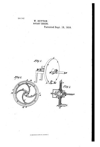
William Sutton's Patent Drawing for a Rotary Engine

National Archives, Restored Patent Drawings (Record Group 241) · Full-size scan at the National Archives · Catalog record
Show the text on the drawing Hide (87 words)
Words on the drawing as machine-read by the National Archives; not checked. Useful mainly for searching.
121 STEAM ENGINES, / Rotary Impact / #1- / William Sutton's / Re / CLASSIFICATION / 8414-x / Kotary Engine / Patented 18.Sep: 1834 / DIVISION. / Fig 1. / Paten to p. 485, / Fig.2 / Fig 3 / billow air / AN / A Case-inclosing the wheel / G Channels / B Induction Pipe / H Concave of the Hub / C Eduction Pipe / I Hollow Axis / D Bim of the wheel / K Box for hollow axis / E Hub / 1. Pulley. / F. Arms / M Oritice. / Heald Me / hat. / Claims hollow Expansion hub, + Lollow in
USPTO scan
The patent as scanned by the USPTO
-
 Page 1
-
 Page 2
-
 Page 3
-
 Page 4


U.S. Patent and Trademark Office · Google Patents
Show the transcription Hide (651 words)
Machine transcription (LightOnOCR) of the pages as scanned by the USPTO, most of them the handwritten copies made when the records were restored after the 1836 fire. Not checked; it can misread handwriting, so compare it with the scan.
Page 1.
8414X
W. SUTTON.
ROTARY ENGINE.
Patented Sept. 18, 1834.
Fig 1.
Fig 2.
Fig 3.
THE MORRIS PETERS CO., PHOTO-LITHO., WASHINGTON, D. C.
Page 2.
8419X Sept. 18, 1854
William Sutton's Rotary Engine
Letters Patent
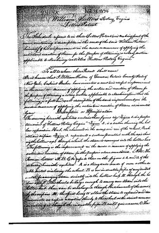
The Schedule referred to in these Letters Patent (and making part of the same) containing a description in the words of the said William Sutton himself of his improvement in the mode or manner of applying …
Page 3.
8419x Sept. 18, 1834
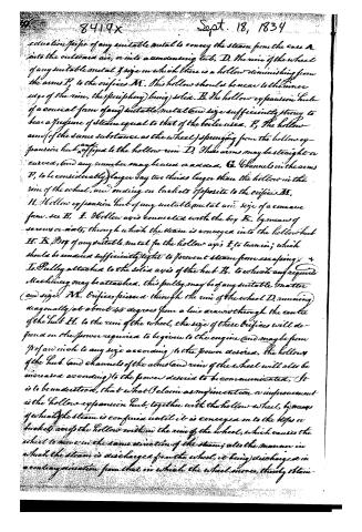
conduction pipe of any suitable metal to convey the steam from the case A into the outward air, or into a condensing tub. D. The rim of the wheel of any suitable metal & size in which there is a hollow diminishing from the arms P, to the orifices M. This hollow should be near to the inner edge of the rim, the periphery being solid. E. The hollow expansion hub of a conical form of any suitable metal & size sufficiently strong to bear a pressure of steam equal to that of the boiler used. F. The hollow arms (of the same substance as the wheel) springing from the hollow expansion hub & affixed to the hollow rim D. These arms may be straight or curved, and any number may be used or added. G. Channels in the arms P, to be considerably larger say two thirds larger than the hollow in the rim of the wheel, and ending on buckets opposite to the orifices M. H. Hollow expansion hub of any suitable metal and size of a conical form. see B. I. Hollow axis connected with the box K. by means of screws or nails, through which the steam is conveyed into the hollow hub H. K. Box of any suitable metal for the hollow axis I to turn in; which should be arranged sufficiently tight to prevent steam from escaping. L. Pulley attached to the solid axis of the hub E, to which any required machinery may be attached, this pulley may be of any suitable matter (and size). M. Orifices pierced through the rim of the wheel D, running diagonally at about 45 degrees from a line drawn through the centre of the hub H, to the rim of the wheel, the size of these orifices will depend on the power required to be given to the engine (and maybe from 1/2 of an inch to any size according to the power desired. The hollows of the hub and channels of the arms and rim of the wheel will also be increased according to the power desired to be communicated. It is to be understood, that what I claim as my invention or improvement is the hollow expansion hub, together with the hollow wheel, by means of which the steam is confined until it is conveyed on to the hips or buckets across the hollow within the rim of the wheel, which causes the wheel to move in the same direction of the steam; all the manner in which the steam is discharged from the wheel, it being discharged in a contrary direction from that in which the wheel moves, thereby obtain-
Page 4.
8414x
Sept 18, 1834
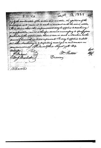
by the combination of the action and reaction, the assistance of the reaction so as to cause it to work in concert with the direct action. It is obvious that this improvement may be applied to machinery in any position; and it is therefore deemed unnecessary to specify more particularly the application than is seen in such a machine as the drawing herewith exhibited represents. It may be applied to mill and other machinery or to propelling carriages on rail roads or on common roads. Philadelphia August 9th 1834.
Witnesses:
J. Dague
Wm. J. Bealock
Wm. Sutton
Drawing
1010 words
Published accounts: journal notice
Notice in the monthly list of patents, with remarks
Journal of the Franklin Institute, new ser., vol. 15 (1835), p. 258 · View the page
25. For a Rotary Steam Engine; William Sutton, Geneva, Ontario county, New York, September 18.
Remarks. The general construction of this steam engine is the same with that of Foster and Avery, patented September 28th, 1831, which, we remarked, (vol. ix., p. 171,) resembled the first which we have upon record, being described in the "Spiritualia" of Hero of Greece. The steam is to be admitted into a wheel with hollow arms, and is to 22 d turn the said wheel by its reaction, as it issues from openings in the rim. To admit steam, the axis upon which the wheel revolves is made hollow, and through this it passes into a hollow hub, thence along the openings through curved arms, and the rim of the wheel; the channels through which it passes being represented by the dark lines in the accompanying sketch. The wheel is to revolve in a hollow metallic drum, as likewise does that of Foster and Avery, above alluded to. The main difference between the wheel before us, and those which have preceded it, is in the "orifices pierced through the rim, running diagonally at about forty-five degrees from a line drawn through the centre of the hub to the rim of the wheel." The patentee says, "It is to be understood that what I claim as my invention, or improvement, is the hollow expansion hub, together with the hollow wheel, by means of which the steam is confined until it is conveyed on to the stops, or buckets, across the hollow within the rim of the wheel, which causes the wheel to move in the same direction of the steam; also the manner in which the steam is discharged from the wheel, it being discharged in a contrary direction from that in which the wheel moves, thereby obtaining, by the combination of the action and reaction, the assistance of the reaction, so as to cause it to work in concert with the direction." We are altogether unable to follow the patentee in his views, or to discover any possible advantage to be derived either from the curvature given to his steam ways, or from the reversed direction of the steam before its exit. Nor can we conceive in what way he secures any extraordinary concurrence of action and reaction; this is certainly the poetical part of the subject, being entirely the work of imagination.
About this record
- Patentee
- DATAMP
- Date
- the Name and Date index of patents, DATAMP, USPTO records
- Invention
- DATAMP
- Listed in
- the Name and Date index of patents, DATAMP, USPTO records, Jim Shaw's X-patent list, the Journal of the Franklin Institute, Burke's List of Patents (1847)
- Burke's 1847 Patent Office list gives the same patent.