

Drawings and documents
National Archives restored drawings: drawing
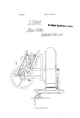
Stephen Ustick's Patent Drawing for a Straw Cutter

National Archives, Restored Patent Drawings (Record Group 241) · Full-size scan at the National Archives · Catalog record
Show the text on the drawing Hide (145 words)
Words on the drawing as machine-read by the National Archives; not checked. Useful mainly for searching.
119. CARE OF LIVE STOCK. / Entered. / Straw Cutters. / L5 / Sliding Knife. / uch / Roller or Apron Feed. / Seephen Unich / Patented Bet's 1834. / Straw butter. butter. / CLASSIFICATION / 8429.4 / Oct. 3. 1834 / DIV ISION. / R. / Jis.2. Indiview. / is / of / w. / S. / feed roll spring / Six. / Preferences. a.a b. base piece c firsteran d eail L seconderant, / If back trough post.g though h.h. feed rollers i seperat box h fastening opposi / m framefor the top feed roller. n.n springs. 0 castoron frame p knife gigregidar / pitman. J. balance wheel. crank. 4 handle v. housontal shaft w. / X.X Catchets y. circl spring I regulating erew. / Palent Office april 19th 18 / the Instion of ch Commisiones of Patents / the act of 3 March 1837 / Menut / of / KD / n. / wish / me and feedroller / Topview: / Section through the line R by
USPTO scan
The patent as scanned by the USPTO
-
 Page 1
-
 Page 2
-
 Page 3
-
 Page 4
-
 Page 5
-
 Page 6


U.S. Patent and Trademark Office · Google Patents
Show the transcription Hide (1,647 words)
Machine transcription (LightOnOCR) of the pages as scanned by the USPTO, most of them the handwritten copies made when the records were restored after the 1836 fire. Not checked; it can misread handwriting, so compare it with the scan.
Page 1.
8429X
Sheet 1-2 Sheets
S. Ustick,
Straw Cutter,
Patented Oct. 3, 1834
No Printed Specification Available
Page 2.
8429X
No Printed Specification Available
Sheet 2 - 2 Sheets
S. Ustick,
Straw Cutter,
Patented Oct. 3, 1834.
Fig. 2
Fig. 4
Fig. 5
Page 3.
XIII w. 40, 24 comm. 1834. Oct. 3, 1834. 41.
Stephen Ustichko
Strawcutter
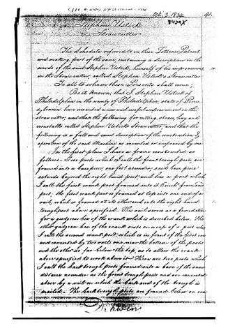
The Schedule referred to in these Letters Patent, and making part of the same, containing a description in the words of the said Stephen Ustichko, himself of his improvement in the Strawcutter, called Stephen Ustichko’s Strawcutter.
To all to whom these Presents shall come;
Be it known, that I, Stephen Ustichko of Philadelphia in the county of Philadelphia, state of Pennsylvania have invented a new and useful improvement on the strawcutter; and that the following for cutting, straw, hay and cornstalks called Stephen Ustichko’s Strawcutter, and that the following is a full and exact description of the construction & operation of the said Machine as invented or improved by me.
In the first place I have a frame constructed as follows—Two posts which I call the front trough posts, are framed into a base piece, one foot asunder; said base piece extends beyond the right hand post; and has a post which I call the first crank post framed into it 6 inch from said post; the first crank post is framed at top into one end of a rail, which is framed at its other end into the right hand trough post above specified. This rail serves as a foundation for a gudgeon box of the crank which is described below. The other gudgeon box of the crank rests on a cap of a post, what I call the second crank post; which is in front of the first one and connected by two rails one near the bottom of the posts and the other as far below the top, as to allow the cranks above specified to work above it. There are two posts which I call the back trough posts framed into a base of the same distance asunder as the front trough posts and are connected above by a rail on which the back end of the trough is nailed. The back trough posts are framed below on one
O. Newton
Page 4.
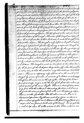
end of two rails which are framed at their other end into front trough posts. The sides of the trough are framed into the front trough posts at one end and nailed at their other end on the inside edges of the back trough posts, the said posts being cut out the thickness of the sides to receive them. The bottom of the trough is in a horizontal position lengthwise. The right hand edge is one inch lower than the left hand one. It extends from the back of the sides of the trough to a fluted cast iron feed roller in front, whose guides turn in the side of the trough just behind the front trough posts. The top of said roller extends 1 inch above the bottom of the trough. The sides of the trough are tapered from the said feed roller to their back end, to make the trough wider behind than before. This trough is only 2 feet in length. I extend the trough 2 feet further by having a separate trough to fit at front to its back, and fastened thereto by having strips of iron fastened on the top edges at front, which extend over the top of the back trough posts and fit by means of holes in their front ends an iron pins which are permanent in the ends of the posts and by a strip nailed on the back of the first trough at the sides and bottom. The trough is made in two pieces as described above for the purpose of the back part being taken off when the machine is not in use, so that the machine may then take up but little room. There is an opposing edge fastened on the mouth of the trough by means of screws, it consists of a bottom and 2 uprights therefrom, the screws are in the uprights. The top of the bottom part of said edge ranges with the top of the feed roller above specified and is of the same height. There is a strip of iron, extending from it to the roller in a descending position, which serves to guide the straw in front of the roller over the opposing edges. There is another feed roller like the above over it. It is in a horizontal position lengthwise and its guides work in a frame whose uprights work between the front trough posts and strips which are fastened to the sides of the trough. The uprights has a rail at top above the roller and one at their bottom which is near
Page 5.
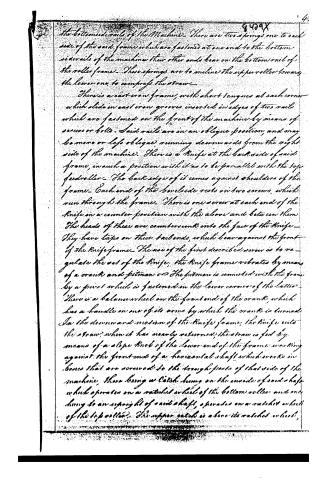
the bottom side rails of the Machine. There are two springs one to each side of the said frame which are fastened at one end to the bottom side rails of the machine their other ends bear on the bottom rail of the roller frame. These springs are to incline the upper roller towards the lower one, to compress the straw.
There is a cast iron frame, with short tongues at each corner which slide in cast iron grooves inserted in edges of two rails which are fastened on the front of the machine by means of screws or bolts. Said rails are in an oblique position, and may be more or less oblique, running downwards from the right side of the machine. There is a knife at the back side of said frame, in such a position with it as to be parallel with the top feed roller. The back edge of it comes against shoulders of the frame. Each end of the blade rests on two screws, which run through the frame. There is one screw at each end of the knife in a counter position with the above and between them the heads of these are countersunk into the face of the knife. They have taps on their tail ends, which bear against the front of the knife frame. The use of the first described screw is to regulate the set of the knife. The knife frame vibrates by means of a crank and pitman. The pitman is connected with the frame by a pivot which is fastened in the lower corner of the latter. There is a balance wheel on the front end of the crank, which has a handle on one of its arms by which the crank is turned. In the downward motion of the knife frame, the knife cuts the straw; when it has nearly returned, the straw is fed by means of a slope knob of the lower end of the frame working against the front end of a horizontal shaft which works in boxes that are screwed to the trough parts of that side of the machine. There being a catch drum on the inside of said shaft which operates on a ratchet wheel of the bottom roller and one hung to an upright of said shaft, operates on a ratchet wheel of the top roller. The upper catch is above its ratchet wheel,
Page 6.
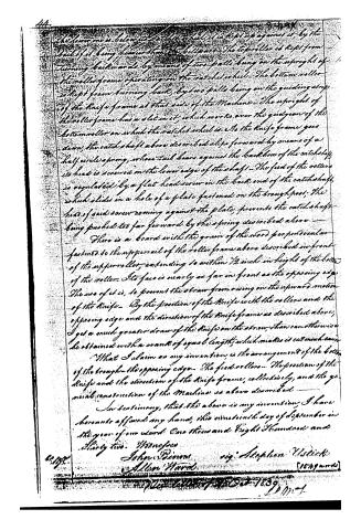
the lower one below the ratchet wheel, it is kept up against it by the tail of it being lower than the bill post. The top roller is kept from turning backwards by means of two balls being on the upright of the roller frame operating on the ratchet wheel. The bottom roller is kept from turning back, by two balls being on the guiding strip of the knife frame at that side of the Machine. The upright of the roller frame has a slot in it, which works over the guide gear of the bottom roller on which the ratchet wheel is. As the knife frame goes down, the catch shaft above described slips forward by means of a half circle spring, whose tail bears against the back box of the catch shaft, its head is screwed on the lower edge of the shaft. The feed of the rollers is regulated by a flat head screw in the back end of the catch shaft, which slides in a hole of a plate fastened on the trough post; the head of said screw coming against the plate, prevents the catch shaft being pushed too far forward by the spring described above.
There is a board with the grain of the wood perpendicular fastened to the upper rail of the roller frame above described in front of the upper roller, extending to within 1/2 inch in height of the bottom of the roller. Its face is nearly as far in front as the opposing edge. The use of it is, to prevent the straw from owing on the upward motion of the knife. By the position of the knife with the rollers and the opposing edge and the direction of the knife frame as described above, I get a much greater draw of the knife on the straw, than can otherwise be obtained with a crank of equal length, which makes it cut much easier.
What I claim as my invention, is the arrangement of the bottom of the trough, the opposing edge, the feed rollers, the position of the knife and the direction of the knife frame, collectively, and the general construction of the Machine as above described.
In testimony, that the above is my invention, I have hereunto affixed my hand, this nineteenth day of September in the year of our Lord One thousand Eight Hundred and Thirty two.
Witnesses:
John P. Davis
Allen Ward
[1579 words]
Published accounts: journal notice
Notice in the monthly list of patents, with remarks
Journal of the Franklin Institute, new ser., vol. 15 (1835), p. 313 · View the page
4. For a Straw Cutter; Stephen Ustick, city of Philadelphia, October 4.
Remarks. There is, we think, considerable novelty in certain parts of this machine, but it has the fault of too much complexity. The straw is to be contained in a trough, in the usual way, and is to be fed by fluted rollers of cast-iron. The knife stands horizontally, or nearly so, across a frame to which it is firmly attached. The lower edge of this frame rests upon ways, which form an inclined plane, and, consequently, as the frame slides, the knife descends with a drawing motion. To cause the frame to slide backwards and forwards, there is a pitman, worked by a crank, on the shaft of a fly wheel in front of the machine. The claim is to "the arrangement of the bottom of the trough; the opposing edge; the feed rollers; the position of the knife; the direction of the knife frame collectively; and the position of the machine, as above described." Although there is enough in this machine upon which to found a claim, the foregoing appears to us defective in claiming individual parts which are not new, instead of depending, almost exclusively, upon the arrangement and connexion of those parts, in which its novelty principally consists. The feeding rollers, as such, are not new; nor is an opposing edge, to resist the cut of the knife. We have carefully looked over the specification, but are far from having a clear idea of what is included in "the arrangement of the bottom of the trough;" if this part contains any thing peculiar, it is not explained. VOL. XV. No. 5.-MAY, 1835.
About this record
- Patentee
- DATAMP
- Date
- the Name and Date index of patents, DATAMP, USPTO records
- Invention
- DATAMP
- Listed in
- the Name and Date index of patents, DATAMP, USPTO records, Jim Shaw's X-patent list, the Journal of the Franklin Institute, Burke's List of Patents (1847)
- The Franklin Institute's journal gives a different date.
- Burke's 1847 Patent Office list gives the same patent.