

Drawings and documents
USPTO scan
The patent as scanned by the USPTO
-
 Page 1
-
 Page 2
-
 Page 3
-
 Page 4
-
 Page 5
-
 Page 6
-
 Page 7
-
 Page 8
-
 Page 9
-
 Page 10


U.S. Patent and Trademark Office · Google Patents
Show the transcription Hide (2,948 words)
Machine transcription (LightOnOCR) of the pages as scanned by the USPTO, most of them the handwritten copies made when the records were restored after the 1836 fire. Not checked; it can misread handwriting, so compare it with the scan.
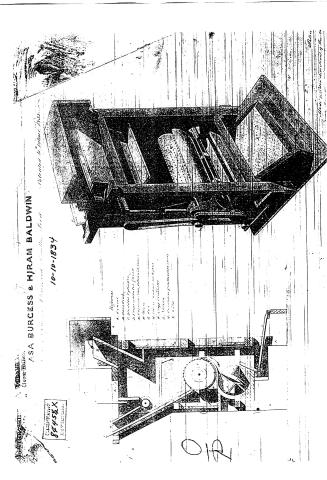
Page 1.
ASA BURCESS & HJRAM BALDWIN
10-10-1834
Classification: 84452X
Patented to John Doe
Figure 1
Figure 2
Figure 3
Figure 4
Figure 5
Figure 6
Figure 7
Figure 8
Figure 9
Figure 10
Figure 11
Figure 12
Figure 13
Figure 14
Figure 15
Figure 16
Figure 17
Figure 18
Figure 19
Figure 20
Figure 21
Figure 22
Figure 23
Figure 24
Figure 25
Figure 26
Figure 27
Figure 28
Figure 29
Figure 30
Figure 31
Figure 32
Figure 33
Figure 34
Figure 35
Figure 36
Figure 37
Figure 38
Figure 39
Figure 40
Figure 41
Figure 42
Figure 43
Figure 44
Figure 45
Figure 46
Figure 47
Figure 48
Figure 49
Figure 50
Figure 51
Figure 52
Figure 53
Figure 54
Figure 55
Figure 56
Figure 57
Figure 58
Figure 59
Figure 60
Figure 61
Figure 62
Figure 63
Figure 64
Figure 65
Figure 66
Figure 67
Figure 68
Figure 69
Figure 70
Figure 71
Figure 72
Figure 73
Figure 74
Figure 75
Figure 76
Figure 77
Figure 78
Figure 79
Figure 80
Figure 81
Figure 82
Figure 83
Figure 84
Figure 85
Figure 86
Figure 87
Figure 88
Figure 89
Figure 90
Figure 91
Figure 92
Figure 93
Figure 94
Figure 95
Figure 96
Figure 97
Figure 98
Figure 99
Figure 100
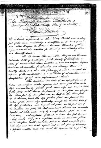
Page 2.
8445 ½ x
Oct. 10, 1835
197
Asa Burgess & Herman Baldwin
Washington, Litchfield County, State of Connecticut,
Letters Patent.
The schedule referred to in these Letters Patent and making part of the same, containing a description in the words of the said Asa Burgess & Herman Baldwin themselves of their improvement in the machine for threshing and cleaning clover and Timothy seed.
Be it known that we Asa Burgess and Herman Baldwin both of Washington in the County of Litchfield in State of Connecticut have invented a new and useful improvement in the machine for threshing and cleaning Clover and Timothy seed, and that the following is a full and exact description of the construction and operation of said machine and specification of the said improvement therein.
The machine consists of an upright frame of timbers about four inches square and seven feet three inches high connected by girders of the same size and covered inside of the posts with boards in panels so as to form an upright box three feet by two feet and a half in the clear from top to bottom, on to the tops of these posts are framed two timbers of the same size extending across the shortest side of the top of the box and beyond the posts on the front side of the machine two feet; the last mentioned timbers are connected together at their outer ends by a roof timber of the same dimensions, and cylinder of wood or iron two feet two and a half inches long and eighteen inches in diameter fitted on its surface with metallic points or teeth one fourth of an inch long and one inch apart, set in the form of diamonds is placed within said box with its eyes on the roof timbers.
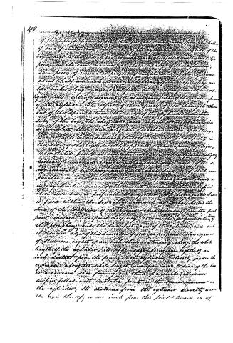
Page 3.
178. 8445
If the upright frame or box, the feet are thus made from the bottom of each frame or box, the ends of the cylinder are the ends of the box nearest to the ends of the cylinder, and also filled with metallic points in the same manner as the periphery of the cylinder. These pieces of iron also project from the ends of the cylinder about half an inch towards the sides of the box. They are too much longer and ramp from their circumference in oblique lines cutting segments of about one foot of the circumference of the cylinder. The effect of these pieces of iron being to throw out of the space between the ends of the cylinder and the sides of the box, the shavings and dust which would otherwise accumulate there and stop the Machine in its operation.
One of us to be mentioned that there are to be two points in the side of the box directly opposite to these pieces of iron. The metallic points above mentioned are made of steel slightly broken flattened and brought to a sharp point. A part of the denomination of the frame, and the metal, is of steel iron punched so as to have both the iron and steel points dead or in any similar manner. The invention consists in the fact that above described is preferable to any other, and a horizontal line is fixed within the box about one inch and a half below the line of the lower line of the cylinder and extending from the front post inward to a point half way between the perpendicular of the periphery and the line of the axis of the cylinder and with the inner edge of this board is fixed a perpendicular groove of steel one eight of an inch thick extending along the whole length of the cylinder, its upper edge being one eight of an inch distant from the points on the cylinder. Directly under the cylinder along its whole length and from side to side of the box is a concave shoe forming one third of a circle, its inner surface filled with metallic points in the same manner as the cylinder. Its distance from the cylinder directly under the axis thereof is one inch from this point towards the
Page 4.
edges it approaches gradually nearer to the cylinder to the distance of three fourths of an inch from the nearest flue. The front or lower edge of the door is attached to the inner side of the quarter by hinges and is supposed to be in the horizontal line of the axis of the cylinder. The door is held open to place in means of an arm of iron or strong wood, each of its ends and being so connected to the convex surface, the arms are connected with the ends of the box near their middle by pivot or pins, and in the lower edge of the quarter, the outer end of the arms being attached to a spring.
Attached to the ends of the box are to help the door in its place and at the same time allow it to yield to any extraordinary pressure which may be made to act upon it, so that this may be made to fall to the sides of the box, the upper edge of the door is brought conveniently to an upright so as to prevent the collection of chaff or other substance and to let the long or white chaff so fallen a thin plate of iron which is turned over horizontally towards the cylinder one fourth of an inch below the front, the means of the door just so far as the teeth and the door.
So much as possible to prevent the chaff and so from falling into the space between the ends of the cylinder and the sides of the box, circular arms are affixed to the ends of the box covering the ends of the cylinder and allowing it to work freely under the teeth. These are of sufficient thickness to cover the space between the ends of the cylinder and the sides of the box and about half an inch of the cylinder, and on each side the cylinder are holes at the ends, and in the same the same should also cover the holes in the arms and are not exposed on their inner side.
Another arm is the upper edge of the door, a space of about two inches between them and the upper edge of the door being left open to allow the chaff and seed which they get into the space between the ends of the cylinder and the ends of the box to work out again from the same aperture in the
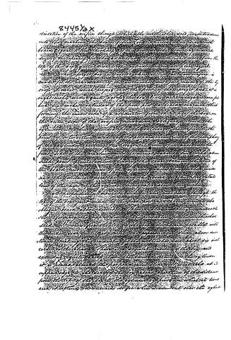
Page 5.
8445½x
direction of the orifice things which the orifice has and is introduced into the machine the line of the orifice is perpendicular to the axis of the board and is the thickness of the board is that the longitudinal edge of the opening for the admission of the orifice is 2½ from the top of the board and down to the cylinder is an angle of 45 degrees.
The orifice has a conical shape and the orifice is made for the admission of the orifice and the point inside of the orifice, the orifice which projects over the point of the orifice and is right-angled and quite near the board its outer edge is one foot due to make outside of the point post a board one inch thick forming the inner side of a conductor from the top of the board on the outer side of the orifice and an oblique line in the cylinder and has extended from the outer side of the orifice to the point of intersection made by the perpendicular line of the orifice of the cylinder and the orifice is the line of the orifice on the first line of the machine and terminates about two inches above such point of intersection being the space between the end of the board and the end of the cylinder and the board is made and the distance from the end of the board to the orifice is the line of the axis of the cylinder being also about two inches.
The perpendicular inner side of the orifice through the top of the board just inside of the first point and from it to the oblique board above is the line of the orifice and the orifice is the forming the orifice and the orifice is the conductor for the orifice and the orifice is the top of the board and is parallel with the inner side and is not the perpendicular side above mentioned making the orifice for the orifice and about 2½ inches in the board. There is a regulator inside of the board and extending quite to the top of the orifice and is the cylinder it is placed close to the perpendicular side of the orifice at its upper edge to the end of the board about one inch of the distance from the top of the board to the cylinder by means which it turns and it extends downwards so far when drawn out over the cylinder.
Page 6.
201.
it is here to be made to receive the air from the cylinder. From the mouth of the cylinder a shaft extends out over the cylinder through the back of the box by means of which the admission of the air to the cylinder is regulated at pleasure.
For the purpose of preparing the air from the shaft and duct of the box passed the cylinder of fly wheel cylinder made in diameter and too for the double long man's seat revolving in a box so that the common joining will be placed between the cylinder so far as to receive freely below the box of the cylinder is connected from the centre toward the first joint of the box and makes the spring into the box for the sake of the same as toward the back part of the inside of the fly wheel is mounted on a base and the box is mounted into the fly wheel at being through a circular orifice in the box which is mounted in the box of the box which is of wood and closely slings as to regulate the admission of air into the fly wheel at pleasure.
The fly wheel with its base or box may also be placed on side of the upright by a stay on the inside to rest on the parts of the upright box of the space between the side of the cylinder and the back side of the box forming the throat for the admission of the air from the fly wheel to the shaft connected in the same manner as in the clear space near the top of the box.
The top of the upright box on the back side of the box is introduced in a manner similar to that of the right side and the clear and opening galleries of the upright box in the same direction as the fly wheel through the bottom of the box and are when separated from the box is driven by the wind from the fly wheel its inner and outer sides of the box and a half long and enters the box on the back side thereof three feet and two inches above
Page 7.
12. 8445XX
The horizontal line of the axis of the cylinder and cylinder down-ward in an oblique direction from the top of the cylinder one foot and eight inches from the top of the cylinder to the bottom of the box, to lower and bring down the water from below of box from the top of the box to the top of the box and back down in the same oblique direction as within the box three feet and a half.
The other three sides of the conductor are to the same height from the top of the box but do not enter it at all. To the outer side of the box of the fly wheel, when it opens to permit the escape of the water from the fly wheel filling the entire space between the two ends of the box and opening below into a view of the pipe below, through which the water after having passed the cylinder through the circuit of air from the fly wheel is allowed into the flow below. The screen is put in motion by means of a wheel ten inches in diameter and is to be connected with a wheel on the side of the axis of the fly wheel properly geared to give it the requisite motion. The rear end of the box below of the upright there are also used to prevent the escape of the shaft and dust from the machine except through the conductor, provided for that purpose. The sides are frames of panels of convenient size and conveniently situated and secured by pins or hinges and bottom so as to admit of being easily removed and replaced when necessary for the purpose of cleaning or repairing the machine or for other purposes.
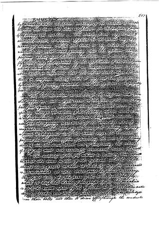
The machine is placed on the lower floor of a two-story building so as to bring just above the floor of the lower story and to the upper end of the perpendicular shaft above the wheel, which rises about three inches above the top of the wheel, a pulley which passes over a block above and thence through the floor into the lower story.
Page 8.
8445708
by means of which the piston or plug of the machine is made to rise and lower to draw or …
Page 9.
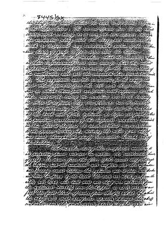
84456x
the shaft and dust which the tube is permitted to fall in to the hopper below. The inner of said fine the fly wheel should not be setting or to any the less open through the conductor along with the shaft and dust are so weak as to permit any considerable portion of the machine's head of graph to fall down into the hopper.
That part of the machine which the inventor claims as their improvement and new and for which they solicit a patent consists of the conductor for the introduction of the machine to do and the movable blade connected with it for the regulation and the conductor for the shaft and dust when separated from the said and the peculiar manner in which these parts are placed with reference to each other and to the rest of the machine and to the bearing in which it is fixed. They also claim as new the peculiar mode of introducing the current of air into the machine at the back end of the cylinder as before set forth, and the peculiar excellence of this improved machine consists in this that it performs its work without inconvenience to the person turning it, among the other of the shaft and dust through the shaft conductor, directly out of the bearing.
The machine being thus completely attached to its supporting frame and set in action the movable head of graph are drawn from the face of the screen stop through the orifices into the conductor and emptied into the cylinder and passing round around the cylinder and to the air box and then in front of the tube the dust and air bags from the cells are sent and the dust is collected and from the cylinder directly into the hopper so as to never and just the full blast of air is forced directly by which the shaft and dust are forced directly through the shaft conductor and the small amount blows into the open air
Page 10.
8445 ½ x
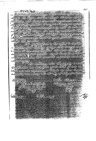
on the outside of the building, while the lead falls down through the hopper into and through the screen into the floor below, and leaves some such very small particles with the use. After this operation it may be necessary or expedient to pass it through a common passing mill in order to make it perfectly clean, or to take any unthreshed heads of grain that fall down through the hopper and pass off over the side of the screen, they are to be again put into the paper through the machine.
The upper frame is to be a firm solid plate on the floor of the building, by key, bolts, or wings, so as to render it immovable and firm. The dimensions of the several parts of the machine may be increased in the same relative proportions, but cannot be materially diminished without injury.
In testimony that the foregoing is a true specification and description of the whole of said machine and our improvement thereon, we have hereunto subscribed our names this 20th day of August A.D. 1835.
Witness:
H. M. Baldwin
David C. Taylor
A. Barger
Herman Helman
3666666666
(9)
End
Mk.
About this record
- Patentee
- the Name and Date index of patents
- Date
- the Name and Date index of patents, USPTO records
- Invention
- the Name and Date index of patents
- Listed in
- the Name and Date index of patents, USPTO records
- The Name and Date index has a note on this number.