

Drawings and documents
National Archives restored drawings: drawing
J. Goulding's Patent Drawing for a Steam Boiler Fire Tube


National Archives, Restored Patent Drawings (Record Group 241) · Full-size scan at the National Archives · Catalog record
Show the text on the drawing Hide (210 words)
Words on the drawing as machine-read by the National Archives; not checked. Useful mainly for searching.
Sheet 1. 122 ST AM-BOILEM. / Introducing Saroke and Gases. / 8471-X / Plate 5. Steam Boiler Fire Tube / J. Goulding / DIV ISION. / Pratented Oct 251834 / 128471784, 2xon 84734 / Fig.3. / Fig.5. / 23 / 27 / 23 / 27 / 19 / 18 / 13 / 23 / Fig. 4 / 32 / 11 / 11 / 31 / 37 / of / Fig.1 / 11 / Vig.2. / 11 / 11 / 11 / $1 16 11 / 16 / 16 / 16 / 30 / If / 28 / 34 / 19 / 36 / 357 33 / 852 / 33 / 23 / ss / 35 / 23 / 76 / 651 / 23 / 11 / 31 / 31 / 16 / 15 / 16 / 18 / 22 / 35 / 15 / ss / 35 / 12 / 26 / 26 / of / 10 / 24 / R.O / 13 / 17 / 14 / 14 / 14 / IT
Sheet 2. 300M3HT WI ТИЗМЗУОЯЯМ 24029MIT2 23MAG / 2J33HW 0A08 JIAR 30 / City of Battimore State of Maryland And. / On this 31st before the Rubscriber, a Justice / appeared Stempson fBaltimore and made solemn / Wheels interested as inventor in a patent for an improvement in the mode of constructing / are as he verify believes, a true delineation ofthe invention, as described in the said / dated 2 32d of October 1834; and the within drawings, the references thereto, / for the use of Rail Road cars or Pacomoline Enginez, sued to him and / Letters patent.- / from to before / James Stimpson / Hyaloh / GT
Sheet 3. J.COULDING'S / 122 ST AM-BOILERS. / Time Zulah Steam Boiler / pibs / Introducing Smoke and Gases. / Patent Oct.25th.1834 / Class 31- Borlers / Plate 1. / Fig.5 / Fig.3. / CLASSI 8471-+ CATION / 11 / 23 / RJ / DIVISION. / 25 / 19 / 23 / 18 / Fig.4. / 23 / 32 / 11 / 11 / 6' / 31 / 31 / Nig. 1 / 7. / DC / 6' / 16 / 11 / Fij %. / Smoker / 13 / of / 16 / 11 / 16 / 16 / 30 / 13 / 11 / as / 33 / 36 / for J out / 35% / 23 / 15 / 2) / 27 / 23 / 6' / 33 / J.J / 16 / 16 / 31 / 27 / 15 / 18 / 15 / Rn / jj / 12 / 26 / 26 / 25 / 10 / 19 / 24 / 25 / RO / 11 / 13 / IT / 17 / 74 / 14 / 14 / Fig.3. / Plate 2. / 15 / Fig.5. / 27 / 19 / 21 / 23 / 23 / 18 / 15 / Fig:4. / on / 13 / 11 / of / 01 / 31 / by / my / Fig.1 / Fig. 2. / 1.3 / 11 / 16 / 16 / 35 / SS / 11 / If / 16 / 16 / 19 / 30 / 11 / The / 28 / 35 / so / 33 / 23 / 14 / 15 / 23 / 11 / is / 13 / 23 / 16 / 31 / 31 / se / 27 / 18 / is / is / Rh / is / 12 / 26 / 26 / 25 / 24 / 14 / 20 / 13 / 14 / 14 / 14
USPTO scan
The patent as scanned by the USPTO
-
 Page 1
-
 Page 2
-
 Page 3
-
 Page 4


U.S. Patent and Trademark Office · Google Patents
Show the transcription Hide (1,996 words)
Machine transcription (LightOnOCR) of the pages as scanned by the USPTO, most of them the handwritten copies made when the records were restored after the 1836 fire. Not checked; it can misread handwriting, so compare it with the scan.
Page 1.
8471X
J. Goulding,
Steam-Boiler Water-Tube.
Patented Oct. 25, 1834.
<!-- Image content: Technical drawings labeled Fig. 1, Fig. 2, Fig. 3, Fig. 4, Fig. 5, repeated three times in a vertical arrangement. -->
AM. PHOTO-LITHO. CO. N.Y. (OSBORNE'S PROCESS)
Page 2.
8471X
UNITED STATES PATENT OFFICE.
JOHN GOULDING, OF DEDHAM, MASSACHUSETTS.
IMPROVEMENT IN THE MODE OF MAKING BOILERS FOR GENERATING STEAM AND EVAPORATING WATER OR OTHER FLUIDS.
Specification forming part of Letters Patent dated October 25, 1834.
To all whom it may concern:
Be it known that I, JOHN GOULDING, of Dedham, in the county of Norfolk and Commonwealth of Massachusetts, have invented, constructed, and applied to use a new and useful Improvement in the Mode of Making Boilers for Generating Steam and Evaporating Water or other Fluids, which improvement is specified in the words and figures following and in the drawings hereto annexed.
The outside of the boiler consists of an upright cylinder of iron or other metal closed at the top and bottom and supported on legs or standards. This cylinder contains a second cylinder, separated from the first by a space at the top and bottom and all around it. The lower part of the second cylinder contains a fire-grate of its own interior diameter. This second cylinder contains a third cylinder whose upper edge or flange is nearly on a level with the upper edge or flange of the second cylinder and connected with it by a horizontal plate or top, which covers all the space between the second and third cylinders, and is securely fixed to their upper edges or flanges. This third cylinder is about one-half the length of the second, and at its bottom there is placed a conical shaped valve. The space from the top or plate which connects the upper edges or flanges of the second and third cylinders to the bottom of the third cylinder and between them is occupied by pipes disposed in strata or horizontal circles, so that the pipes do not touch each other, nor is any pipe exactly over a pipe in the tier next below it. The inner ends of these pipes are tightly screwed into the third or inmost cylinder. The other ends are fastened into the second cylinder by nuts on its inside and outside. The lowest of the rows of these pipes may have an inclination downward from the bottom of third cylinder. From the plate or top connecting the upper edges of the second and third cylinder tubes or pipes are carried to or through the top of the first cylinder for smoke-pipes. From out the top or head of the first cylinder a funnel is raised, which is a steam-chamber. From the chamber a steam-pipe issues. Above the fire-grate the second cylinder may be lined all around up to the ends of the lowest row of pipes, excepting the doorways, with soapstone or pipe-clay brick.
Under the fire-grate may be a finer grate or sifter. At the bottom of the first cylinder there is an aperture opening into the space between the bottoms of the cylinders which may be closed by a head-piece. Over this aperture and in the outside cylinder is a door, over this door another, and over the second a third. These doors communicate with the fire-chamber and with the ash-chamber under it. When this boiler is to be put in operation the fuel may be put upon the grate through the doors marked 8 and 9 in the drawings hereunto annexed. The space between the first and second cylinders to near the top or head of the former. The third or inmost cylinder with the pipes between the second and third cylinders are to be filled with water. By the application of heat the water will be immediately put in motion, and rising in the inmost cylinder will flow over into the space between the first and second cylinders and through the pipes into the inmost cylinder again. The circulation thus created will be continued as long as the heat is applied. The heat and smoke will pass up between the second and third cylinder among the pipes, and the smoke will pass off through the smoke-flue.
The above is a general description of the boiler as improved by me. The boilers may be of any size and contain any number of pipes, and the actual and relative size of the parts may be varied as different purposes may require; but I subjoin a detailed description of one of my boilers six feet in height as explanatory of the mode of constructing them, which for that purpose, with the plates annexed, may be taken as part of this specification.
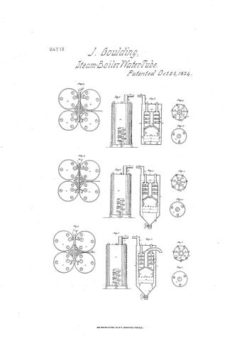
Figure 1, Plate 1, represents a boiler externally when in position and readiness for use. 15 is the first cylinder or outside case, six feet high and thirty inches in its external diameter. 16 is its top or head, of which a bird’s-eye view is given in Fig. 4. 17 is its bottom, and 14 14 are the feet or the standards which support it. 7 is the steam-chamber, about six inches in diameter. 6 is the steam-pipe, from one to two inches in diameter. This steam-chamber and pipe form an outlet for the steam, and on the top of the former a safety-valve is placed. 11 11 11 are the tops of the smoke-
Page 3.
pipes raised above the top of the case. 16 8 9 10 are doors each six inches high and six wide. 8 is the fuel-door, through which the grate is generally supplied. 9 is to be used, together with 8, when all the fuel is to be taken out. 10 is the ash-pit door, through which the ashes are removed. 13 is the aperture through which the space between the bottoms of the first and second cylinders may be cleansed. 12 12 12 are door-latches.
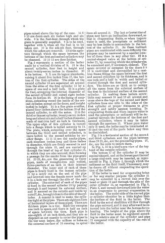
Fig. 2 represents a section of the boiler made by a vertical division of it. 18 is the second cylinder, four feet in height and about twenty-seven inches in diameter. 20 is its bottom. X X are its legs or standards, raising it about five inches from 17, the bottom of the first cylinder. The sides of the second cylinder 18 are separated all around from the sides of the first cylinder 15 by a space of one and a half inch. 25 is a grate for fuel, occupying the internal diameter of the second cylinder and raised eight inches from its bottom 20. 26 is the lining of soapstone, extending round the inside of the second cylinder, except at the doors, and is eight inches in height. 24 is a fine grate or sifter, placed four inches above the bottom 20 of the second cylinder, to sift the ashes. 21 is the third or inmost cylinder, twenty-seven inches long and about six and a half inches diameter, made of cast-iron half an inch in thickness. The upper edge of this cylinder is turned into a flange which is bolted securely to 19. The plate, which, extending over the space between the third and second cylinders, is there bolted to the second cylinder by another flange. 11 11 11 are the smoke-pipes, each nineteen inches long and three inches in diameter, which are firmly secured in and through the plate 19, and are carried up through the head of top of first cylinder 16, to which they are also secured, thus forming a passage for the smoke from the pipe-grate 25. 23 23, &c., are the generating or water pipes, made of wrought-iron and welded, three-quarters of an inch in their internal diameter. The inner end of each of these pipes is firmly fixed in the inmost cylinder 21 by a screw cut on the end of the pipe and screwed into the female screw made for it in a hole cut through the side of the said cylinder. The outer end of each of the pipes is fixed in the second cylinder 18 by passing through it and beyond its external surface, and is secured on the outside and inside by nuts 27, &c., brought close to the side of the cylinder. A cement is used to make the cylinder tight at the pipes. There are eighteen tiers of horizontal layers of these pipes. There are thirteen pipes in a tier. Each tier occupies one inch in space, and there is half an inch of space between the tiers. Each pipe is one-eighth of an inch thick, and they are so disposed as not exactly to cover the pipes in the tier next below, the orifices or holes on the external surface of 18 running in spiral lines all around it. The last or lowest tier of pipes may have an inclination downward, so that in evaporating fluids, or when impure water is used, the precipitate or sediment may be less liable to accumulate in the bottom of the cylinder 21. As these inclined pipes are constructed with more difficulty the purpose may be answered by a smaller number of them than in any other tier. 22 is a conical-shaped valve at the bottom of cylinder 21, by removing which the cylinder can be examined and, if necessary, cleaned. The space covered or occupied by the doors 8 9 10 is undivided and surrounded by a cast-iron frame filling the space between the first and second cylinders by its thickness, and is one inch and a half in width and bolted or riveted through the first and second cylinders. The doors are so thick as to occupy all the space from the external surface of the first to the internal surface of the second cylinder. In making these boilers screw-bolts may connect 15 and 18 all around and cross above the tops of the second and third cylinders from one side to the other of the first cylinder at proper distances to give strength and safety against bursting. In evaporating fluids and when impure water is used the precipitate or sediment will be deposited between the bottoms of the first and second cylinders, where it may be taken through the aperture 13. Where pure water only is used, the boiler may be terminated at 29 and the cost of the parts below may thus be diminished.
Fig. 3 is a horizontal section of the second and third cylinders and the pipes between them 23 23, &c., are the generating-pipes. 27, &c., are the nuts to secure them.
In Fig. 4, 16 is a bird’s-eye view of the top head of the outside cylinder.
The bottom 17 of the cylinder 15 may be conical-shaped, and at the lowest part thereof a large stop-cock may be inserted, as represented in Fig. 2, Plate 2, through which the sediment or the fluid itself, if necessary, may be drawn off without suspending the operation of the boiler.
If the boiler is used for evaporating brine or for any similar purpose the cylinder 21 may be extended in a curved line over the head or plate 19 and through the side of the outer cylinder 15, as represented in Fig. 2, Plate 3, and turned downward into the water in an evaporator to prevent evaporation in the boiler. The under side of the curved pipe or cylinder shoulder be a little higher than the surface of the fluid in the boiler. The fluid by the act of ebullition will flow through the pipe outward, and it may afterward be returned into the boiler near the bottom for reheating. The height of the pipe above the fluid in the boiler must be regulated according to relative size of the cylinder and pipe 21 compared with the capacity of the rest of the boiler.
Page 4.
8471X
That part of the above-described boiler which I herein claim as my improvement, and for which I now claim Letters Patent, is—
The extension of the cylinder 21 over the head or plate 19 and through the outside of the cylinder 15, so that the water or other fluid when raised above a boiling heat may be thrown out of the boiler by its own ebullition.
JOHN GOULDING.
Witnesses:
HORACE MANN,
CHARLES EDWARD RAHN.
Published accounts: journal notice
Notice in the monthly list of patents, with remarks
Journal of the Franklin Institute, new ser., vol. 15 (1835), p. 331 · View the page
45. For Boilers for Generating Steam; (No. 1) John Goulding, Dedham, Norfolk county, Massachusetts, October 25.
Remarks. This is to be a vertical, cylindrical boiler, the furnace and ash pit of which are situated at its lower end, much in the manner of the ordinary cylindrical stove. There are to be two interior cylinders concentric with that which forms the exterior of the boiler, but which are to terminate at some distance below its upper end; these two cylinders are to be connected together by a covering close at top, but not passing over the inner cylinder, as the water to be heated is contained between the outer and second cylinder, and is to flow over into the interior cylinder, which is closed at its lower termination over the fire. The flame and heat from the fuel pass up through the space between the interior cylinders, and the smoke escapes through pipes attached to the plate which closes their upper ends. A great number of tubes, open at each end, cross the space between these two cylinders, opening a free passage between the interior of the inner cylinder, and the space between the outer and second cylinders. These tubes are arranged spirally, so that one shall not directly cover another, and obstruct the general action of the heat from the fire. In the specification, certain proportionate dimensions are given, but as these are not essential o the principle, we need not insert them, nor is it necessary to describe those subordinate parts, or modes of connexion, the necessity for which will be understood by those interested in the subject. These are all perfectly well represented in the drawings accompanying the specification, leaving nothing to desire in this particular. The claim is to "the arrangement and combination of the second cylinder, with a third cylinder, and the pipes between them; all being placed within an outer case or cylinder; and for said arrangement and combination I herein claim letters patent." The boiler given as an example has the outer cylinder six feet high, and two feet six inches in diameter. The second cylinder is four feet in height, and two feet three inches in diameter, its bottom reaching within about five inches of the bottom of the outer cylinder, and being supported upon legs. The inner cylinder is two feet three inches long, and six and a half inches in diameter, its top edge being, of course, even with the top edge of the second cylinder. The smoke pipes ascend from the covering of the two inner cylinders, and pass through the top of the boiler. In the great variety of forms which have been given to steam boilers, there are some which, in part, resemble that before us; we think, however, that it possesses enough of novelty to sustain a patent. Whether the circulation of water within it will be such as to prevent incrustation in the tubes, and to obviate other difficulties which have been encountered in the employment of tubular boilers, is a question that must be decided by the test of experience; we know that a favourable opinion is entertained respecting them by some persons of judgment, and we hope that this opinion may be found to be correct.
Published accounts: journal notice
Notice in the monthly list of patents, with remarks
Journal of the Franklin Institute, new ser., vol. 15 (1835), p. 332 · View the page
47. For Making Dry Steam, or preventing water from passing or going over, out of a Boiler into a Steam Pipe; John Goulding, Dedham, Norfolk county, Massachusetts, October 25.
About this record
- Patentee
- the Journal of the Franklin Institute, Journal
- Date
- the Name and Date index of patents, USPTO records
- Invention
- the Name and Date index of patents
- Listed in
- the Name and Date index of patents, USPTO records, the Journal of the Franklin Institute, Burke's List of Patents (1847)
- The patentee's full name comes from the Franklin Institute's journal.
- Burke's 1847 Patent Office list gives the same patent.