

Drawings and documents
National Archives restored drawings: drawing
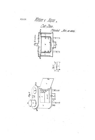
T. Whitson and G.E. Haynes' Patent Drawing for a Portable Cooking Stove


National Archives, Restored Patent Drawings (Record Group 241) · Full-size scan at the National Archives · Catalog record
Show the text on the drawing Hide (89 words)
Words on the drawing as machine-read by the National Archives; not checked. Useful mainly for searching.
Sheet 1. Stane STOVES & FURNACES / Scad Ed / Cooking / [154] Cooking Stoves. / Colorifies / $2- / classification / T.WHITSONG.E.HAYNE'S / 850 3-+ + / DIVISION. / Portable cooking stove. / 1834 / Patented Nov 19th 1854 / Fig.1. / Fig.2. / SI, / Hd / I, / DDD / Fig.3 / DP / R.R. / by
Sheet 2. 12- / 126. STOVES & FURNACES / [154] Cooking Stoves. / T. WHITSON and G.E.HAYNE'S / CLASSIFICATION / 8503 X / DIVISION. / Portable Cooking Stove. / Patented Nov. 19th 1834. / Fig.1. / Fig. 2 / DD D D D / E. / to / Fi.g.s. / sis / RR
USPTO scan
The patent as scanned by the USPTO
-
 Page 1
-
 Page 2
-
 Page 3
-
 Page 4
-
 Page 5
-
 Page 6
-
 Page 7


U.S. Patent and Trademark Office · Google Patents
Show the transcription Hide (1,899 words)
Machine transcription (LightOnOCR) of the pages as scanned by the USPTO, most of them the handwritten copies made when the records were restored after the 1836 fire. Not checked; it can misread handwriting, so compare it with the scan.
Page 1.
8503X
Whitson & Hayne,
Cook Stove.
Patented Nov. 19, 1834.
Fig. 2. Section
Fig. 3.
Fig. 1.
Page 2.
11/17/1834 6505X
Nov. 19, 1834 133.
Thomas Whitton & Gustavus Edwin Haynes.
The schedule referred to in these Letters Patent, and making part of the same, containing a description in the words of the said Thomas Whitton and Gustavus Edwin Haynes, themselves, of their improvement in the construction of cooking stoves, called the Portable Cooking Stove.
To all to whom these presents shall come—Thomas Whitton, Grate and stove maker, and Gustavus Edwin Haynes, Iron plater, both of Roxbury, in the county of Norfolk, and Commonwealth of Massachusetts and Greeting—
Be it known, that we the said Whitton and Haynes, have invented, made, constructed, and applied to use, a new and useful improvement in the construction of cooking stoves, which we denominate the portable cooking stove—which said invention and improvement we specify, and describe as follows namely:
The drawing hereto annexed contains a delineation of our said improvement, Figure numbered One, represents a perspective view thereof. Figure numbered two, represents a sectional view of the same. Figure numbered three, represents the grate herein after described. The same letters in the different figures represent the same parts as far as they are shown. A.A.A. represents the body of the stove. B.B.B. represents the legs by which the stove is supported. C. represents the door of the oven. D.D.D. is the top of the lower chamber. E.E. are bars placed across each end of the oven, upon which bars may be placed other bars lengthwise of the oven when what articles are placed while cooking. F.F. are hollow pipes for conveying the heat and smoke from the lower chamber, into the upper chamber. G. is the iron of the stove. H.H. are the handles connected with two doors, H.H. which are used to prevent, as may be required, the heat
Page 3.
from ascending into the upper chamber. KK is the upper chamber. I I are openings in which boilers are to be placed, and in figure numbered one M represents a boiler placed in one of them. M represents the funnel through which the smoke reaches. N N represents fenders of sheet iron or other suitable material, placed within the oven, perpendicularly against said pipes and fastened thereto by means of projections or flanges used to prevent the heat from striking too suddenly on the food while cooking, and to diffuse the heat over the oven. O is a fender of sheet iron or other suitable material, placed near the top of the lower chamber and rivelled or fastened to the sides of the chamber to prevent the heat from striking too suddenly against the bottom of the oven, and to cause the oven to be heated more uniformly. P is the handle connected with the grate QQ, which contains the fire. The grate is composed of cast iron with bars a a, placed in the bottom sufficiently near each other to prevent the fire from falling through, and yet to permit the ashes to escape. The grate is rectangular and has four legs, b b, upon which it is supported, and the front there is an opening RR, to allow of a draft of air, with the exception of the draft above named, the whole grate is made to fit into the meager or pan SS, which is placed underneath the body of the stove, and nearly in the middle thereof, and is used to receive the ashes from the coal or wood. The meager or ash pan by means of flanges c c, is fastened to the bottom of the body of the stove. There is also an aperture in the bottom of the stove directly over the place where the meager or ash pan is fastened thereto, and communicating with the lower chamber. This aperture is about half the whole length of the grate from the side of the stove. The body of the stove may be cylindrical, cubical, rectangular or oval, and of any convenient size. It may be made of sheet iron or polished tin, or other suitable material. We prefer polished tin. The ordinary size which would be required is twenty-four
Page 4.
inches long, fourteen wide, and fourteen high. The legs are of iron or other suitable material, and are joined across the bottom of the stove in order to give strength and firmness to it, and are about ten inches long. The receiver or ash pan of a stove of the dimensions before named is nine and one quarter inches long, and five and one quarter wide, and five and one half deep, and is placed as near as may be in the center of the bottom of the stove, so that the mouth thereof shall be nearly even with the fronts of said stove. In larger or smaller sizes it should be made in proportion. It is made of stiff sheet iron or other suitable material. The grate is of cast iron, and for a stove of the above size should be made nine inches long, five wide, and three and a half deep, and resting on four legs or supports, and when placed within the receiver or pan, should be made with the exception of the opening, for a draft to close the whole front of the pan. The bottom chamber occupies the whole space between the bottom of the oven and the bottom of the stove, excepting that a very small space about one inch wide, may be left in the front and rear of the oven, for the purpose of fastening it to the bottom of the stove. The lower chamber in the size above named is two and one half inches deep. The oven occupies the whole space between the two chambers excepting what is occupied by the two pipes. This is ten inches deep, any number of bars may be placed across each end of the stove that may be required, and on these, other bars are laid lengthwise of the oven on which the food required to be cooked is placed. The pipes pass from one chamber to the other, and may be either cylindrical, oval, or of any other suitable shape. We prefer those that are oval, as we think they occupy less space, and in other respects answer the purpose equally well. In the size before mentioned the pipes are four inches diameter, and ten inches long. The upper chamber occupies all the space between the top of the
Page 5.
136
oven and the top of the stove, and on the side (as is mentioned), is about two and a half inches deep. The fenders (A) are four inches wide, and extend nearly to the top of the pipes to which they are fastened. The fender (C) which prevents the heat from coming directly against the bottom of the oven is four and a half inches wide, and six inches long, and is fastened at each end to the sides of the oven, the ends being turned up so as to leave a space between it and the bottom of the oven. The dampers are made of sufficient size, and are so constructed and placed in the upper chamber as when closed to cover entirely the two pipes. The openings for the boilers are about nine inches in diameter in a stove of the size above described, and when no boilers are used the openings are stopped by a sheet iron or other covering, and when the stove is not wanted for boiling it may be made without the openings. The smoke pipe is about four and a half inches in diameter. The door of the oven is fifteen inches long, nine and a half inches high, and is made to turn on hinges, and to close entirely the mouth of the oven. The aperture on the bottom of the stove is four and a half inches wide, and ten inches long. We do not however restrict ourselves to the particular dimensions herein before named. We believe however, that for the size mentioned, the different parts are well proportioned, and that they should be made larger or smaller, according to the size of the stove to be used. When the stove is made of polished tin or other polished material, it retains almost all the heat within itself, but when made of sheet iron or other material not polished, the heat passes off, and would warm or heat the apartment in which it is placed. The different parts of the stove are put together by means of rivets or nails in such a manner that the heat will not defat them. The above stove is calculated for the burning of charcoal, bituminous or anthracite coal or wood. When the latter is used
Page 6.
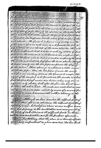
the grate is disposed with and a door with a suitable flue for a draft may be used to close the receiver or ash pan. The coal is placed in the grate, and the heat and smoke produced by the burning thereof passes through the aperture in the bottom of the stove, and the heat strikes against the fender O, and from that is radiated and diffused over the whole of the surface of the lower chamber. The fender O is placed only directly over the grate and is open on both sides, so as to permit the heat to pass between it, and the top of the lower chamber. This will produce sufficient heat to bake or cook any articles of food placed in the oven, and will produce an uniform heat, so that the food will be baked or cooked uniformly throughout. The smoke and heat also pass from the lower chamber through the pipes, nearly over the two pipes are placed the openings for the boilers. These openings are placed a little nearer the smoke pipe, than the two pipes, because the smoke and fire air rushing towards the funnel to escape. The object of the dampers is to permit all the smoke and heat from the fire, to pass under one boiler, when only one is required, or by shutting both after the fire has burnt down to retain the whole heat. The smoke and waste heat are carried off in the smoke pipe, which by means of a common funnel may be made to communicate with a chimney or the open air.
Although we have described the different parts of the said stove, yet we do not claim the different parts thereof separately as new, but what we claim as new and our invention and discovery, is, the construction and arrangement of the whole of said stove, and its different parts in the connection and combination, and for the purposes aforesaid—
In testimony that the above is a true specification of our said improvement as above described, We have hereto
Page 7.
Set our hands this thirtieth day of November in the year of our Lord one thousand eight hundred and thirty four.
Witnesses:
Col. A. H. Drake 3
M. Frances Gardner 3
Thomas Whitson
Gustavus A. Maynes
Drawing
Patented November 19th 1834
About this record
- Patentee
- Jim Shaw's X-patent list
- Date
- the Name and Date index of patents, USPTO records, Jim Shaw's X-patent list
- Invention
- the Name and Date index of patents
- Listed in
- the Name and Date index of patents, USPTO records, Jim Shaw's X-patent list, Burke's List of Patents (1847)
- Burke's 1847 Patent Office list gives the same patent.