

Drawings and documents
National Archives restored drawings: drawing
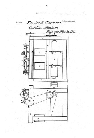
William Fowler and R.M. Germond's Patent Drawing for a Machine for Twisting Roving

National Archives, Restored Patent Drawings (Record Group 241) · Full-size scan at the National Archives · Catalog record
Show the text on the drawing Hide (44 words)
Words on the drawing as machine-read by the National Archives; not checked. Useful mainly for searching.
He ordage SA / WM FOWLER & R.M. GERMOND. / 19. Dana / 118 SPINNING. / #achine for Twisting Roving. / $4 Throsties and Caps. / Patented Nov. 24'81834 / Throstles - Caps / 8505-4 CLASSIFICATION / DIVISION. / h. / op
USPTO scan
The patent as scanned by the USPTO
-
 Page 1
-
 Page 2
-
 Page 3
-
 Page 4
-
 Page 5
-
 Page 6
-
 Page 7
-
 Page 8


U.S. Patent and Trademark Office · Google Patents
Show the transcription Hide (2,641 words)
Machine transcription (LightOnOCR) of the pages as scanned by the USPTO, most of them the handwritten copies made when the records were restored after the 1836 fire. Not checked; it can misread handwriting, so compare it with the scan.
Page 1.
8505X
Fowler & Germond,
Carding Machine.
Patented Nov. 24, 1834.
2 Sheets. Sheet 1.

Page 2.
8505X
Fowler & Germond,
Carding Machine.
Patented Nov. 24, 1834.
2 Sheets, Sheet 2.
Page 3.
11/27/1837 0005X
Nov. 24, 1834
William Fowler & Richard M. Germond, of Union Vale, N.Y.
Letters Patent
The schedule referred to in these Letters patent, and making part of the same containing a description in the words of the said William Fowler & Richard M. Germond, themselves, of their improvement in a machine for twisting roving from the several spindles on which roving is condensed.
To all persons to whom these presents shall come: Be it known, that we William Fowler & Richard M. Germond, of Union Vale, in Dutchess County, in the State of New York, have invented a new and useful machine for twisting roving made on the several spindles on which roving is condensed by counter twist, by rubbing, or made in any way without twist, and that the following is a full and exact description of the construction and operation of the said machine, as invented or improved by us. Note—in the following description of this machine that side having on it the spindles, will be called the front side, and the opposite the back side. That end having the driving pulleys will be called the pulley end, and the opposite the gear end. This machine consists of a frame two and an half feet wide, three feet high and its length must correspond to the number of spindles employed in it, and will require about six inches for each spindle, which number may be six or more as desired. This frame work consists of 4 posts, with girths, all round near the bottom, and near the middle with plates on the top of the posts across each end. A plank one foot wide, connects these plates on the back side. A beam also connects these plates, leaving a space between the plank and beam, of seven and a half inches. Forward of this beam is the rail for the guide wires, having its upper surface two inches below the top of the beam. To the front edge of this rail is the faller rib, connected with it by bolts or hinges, so that the guide wires, in the front edge of the rib will be brought directly over the center of the spindle. This frame work is marked A, and the rib containing the guide wires, is marked a. The front lower girth forms the step rail and is marked D. The front middle girth is four and an half inches wide, and is framed into the posts and middle end girths, and the front edge comes directly over the middle of
Drawing
Page 4.
the step-rail or centre of the steps, and forms the spindle rail or upper bearing of the spindle, which are let into it, one half their diameter. On the front edge of this rail is screwed the spindle caps, which, with the spindle rail completely enclose the spindles, and is brought flush with the front side of the posts, and is marked b. All these parts and pieces, being thus arranged and adjusted, the spindles are entered in their steps & bearings. These spindles are marked c. and are in form below the bearing similar to the common English line spindle with its whist to give it motion, but above the bearing it is wholly new, and our invention consists of a simple pin seated to the side of the hole in the bobbin through which it is to pass, and is formed by a continuation of the stem of the spindle above the bearing, and enclosed within a tin can or cup of sufficient diameter to receive within the bobbin, when placed on the pin and leaving a space of half an inch between the periphery of the bobbin and the inside of the can. This can or cup is open at the top, and has a bottom of tin, with a flange of the same, extending downwards to the bearing and enclosing the pin of the spindle to which it is firmly soldered. The can may be raised a small distance above the bobbin and pin. Two bearings with caps are then fitted in the front side of each back post marked c. about thirteen inches upwards from their feet. The main shaft is then fitted in these bearings marked D. having on its pulley end outside of the frame a post and loose pulley of seven inches diameter, and three inches on the face, and are the driving pulleys of the machine marked E. and on the gear end, outside of the frame, a pinion cog-wheel of twenty-six teeth marked d. and between the posts this shaft has upon the main cylinder extending the whole length of the line of the spindles, and may be seven inches in diameter and is marked d. From the middle girth on the gear end, a small distance forward from the back post, a stand is bolted, projecting downwards, and having in it a stud projecting outwards, and receiving upon it a cog-wheel of eighty teeth marked e, to match and gear into the pinion-wheel on the main shaft. This stud wheel has on its hub a pulley of six inches diameter and one & a half inch on the face marked f. A shaft is next placed in bearings in the top plate, on each end of the frame in such a manner as to bring the shaft exactly
Page 5.
in the middle of the space between the top plank and beam before mentioned, and a little lower than the top of the plate. On this shaft (which is marked g.) on the gear end is a pulley of seven and half inches diameter marked g. and in a line with the pulley f. on the hub of the cog-wheel c. and on this shaft and in a line with the spindle, are an equal number of winding blocks marked H.H. of six and three quarter inches diameter and of a length to play freely between the heads of the bobbins, to be fixed with the roving when twisted. At a small distance from each of these blocks a crooked stand is raised having one foot of each bolted to the top plank and the other foot to the beam, and their legs are raised in a circular manner and united at a height of the upper surface of the winding blocks and directly over the shaft at this point of union they are projected upwards and slotted to receive the pins on which the bobbins are fixed, and to serve as a guide for them to turn and rise in as they fill. These stands are marked h. the pins upon which the bobbins are placed while winding, pass through the centre of the bobbin, and have on one end of each pin a second pulley of one and an half inches diameter. A traverse frame is then framed about fourteen inches wide and extending the whole length of the line of blocks with room to traverse marked d. The back side of the front piece of this frame is even with the back side of the beam, and rests and slides upon it. The back piece of the frame rests and slides upon the plank, and these pieces are held together by joints connecting the ends; a slit is made in each side piece of this frame at opposite ends of sufficient length to permit it to move endwise, the length of the bobbins, and of sufficient width to pass freely on a steady pin in the plank and beam which it receives, and which serves to guide its lateral motion. On the front piece of this carriage are a number of guides or grooves equal to the number of bobbins to be filled. These guides are marked i. Two crooked stands are then raised from the plank. The first may be about fourteen inches inwards from the gear end, and the other thirteen inches from the first. The front feet of these stands may be even with the front edge of the plank. The other feet may be one and half inches back of the back piece of the traverse carriage. These feet are bolted to the plank, and rising in a circular form are united directly over the centre of the back piece of the carriage, leaving under them
Page 6.
a sufficient space for this piece of the carriage to move freely. They are then projected upwards and form the bearings for the double screw shaft not described, these stands are marked j. a shaft is then entered in these stands four and an half inches high from the plank marked K. having on its gear end a cog wheel of sixty-four teeth, and from this cog wheel towards the pully end a double traverse screw of sufficient length to give a traverse motion the whole length of the bobbin between the heads and is marked L. a small stand is then raised from the back piece of the traverse carriage and turned horizontally about two inches, and through this stand a traverse guide is passed having its bearing in the stand, and its stop in the top of the back piece of the carriage. The upper part of this guide is circular and is fitted into the grooves of the screw and is marked l. Two upright stands are then raised near each end of the plank on the back part marked m. to the same height with those holding the screw shaft into these stands a shaft marked M. is entered having on a scored pully of 2¼ inches diameter marked n.n.n. in a line with each pully on the pins of the bobbins, and a cog wheel marked N. of twenty-six teeth in a line with, and to match and gear into the cog wheel on the screw shaft. When all the before mentioned parts & pieces of this machine are thus adjusted, and the gearing before mentioned all entered in gear (all which gearing is of the kind commonly called spur gearing and may have about 10 teeth to each inch of the diameter of each wheel). A strap or belt is passed round the pully on the hub of the cog wheel c. and around the pully on the shaft of the winding blocks, and a band is passed and crooked around each pully on the bobbin pins and each pully on the shaft M. corresponding to them. And bands are also passed round the main cylinder and each of the spindle wheels. Then place a bobbin of roving to be twisted upon each spindle within the can, and an empty bobbin upon each of the winding blocks, unwind a small piece of roving from each bobbin on the spindles, give it a slight twist with the hand, pass it through the guide wire over the spindle & through the guide, on the traverse carriage, and attach it to the bobbin on the winding blocks. Then pass a belt from the driving power of the mill around the fast main pully and all will
Page 7.
be in motion. The roving from the bobbins on the spindles will be thrown from the bobbins on the spindles by the action of the centrifugal power gently against the inner side of the cans, from whence it will be drawn by a slow motion through the guide wires and guides, to the receiving bobbins on the blocks, receiving as it passes a proportion of the twist equal to the relative motion of the spindles with that of the winding block which may be adjusted to any quantity of twist desired by the operator. The receiving bobbins will be moved by the friction of the blocks. The shaft No. will be moved by the bands from the pulleys on the bobbin pins, acting on the pulleys n.n.n. The cog-wheel N. gearing into the cog-wheel on the screw shaft will cause the shaft to turn the worm will force the guide connected with the traverse carriage will, be moved towards that end of the screw to which its diagonal grooves tend until it arrives at the extreme point, when by the common reverse movement it is changed into the grooves of the reversed screw, when it will be carried back again to the extreme point at the other end when it will be again changed, and this guide and with it the carriage to which it is attached, will be moved in this manner while the machine operates, and the guide grooves on the front piece of the carriage, will be caused to pass and repass in front of the receiving bobbins on the blocks, and will distribute the threads of roving passing between them evenly between the heads of the bobbins, until they are filled when they must be doffed and replaced with an empty set as the bobbins on the spindles become emptied of their roving they can be taken out and full ones put on the spindles, without stopping them. Also, the machine may be doffed without stopping if the operator see fit. Note: The motion of the spindles must be contrary to the motion the bobbin had while filling upon the speeder on which it was originally made, or it must have the same motion which would be given to it by drawing off the roving from it when on the spindle and the spindle free to let it turn. The advantages of this machine will be obvious to all who have used the roving from the various condensing speeders, condensing by counter twist or by rubbing, and the many attempts which have been made to impart the necessary strength to those rovings, show the importance of the result now obtained, and by using this
Page 8.
206
simple improvement, the saving in all respects, better than that from the geared speeder or fly frame, is obtained, and the great expense of those frames saved to the manufacturer. As many parts of this machine have been long known, as the traverse and winding motions, and others, we therefore to the invention of those parts separately lay no claim whatever, but what we do specifically claim as our invention, is all the parts and arrangement of the spindle above the bearing, consisting of the can or cup as arranged and fitted for turning the bobbin and the principal and method of throwing off the roving from the bobbin by the action of the centrifugal power of its motion and sustaining it against the inside of the can until drawn away by the receiving bobbin and imparting to it during this process any quantity of twist, as before described. And we also claim the other parts of this machine as combined with the new parts invented by us and the general arrangements of these parts as before described by which we have produced a new and useful process or series of machinery now before known or used, and we claim these new and combined parts as united in these machines not only in the proportion above described, but in any or in all proportions in which the principal discovered and invented by us may be useful.
In testimony that the foregoing is a true specification or description of our said improvement and invention we have hereunto set our hands, this 29th day of July 1834.
Witnesses,
Thos. Vosburgh
Isaac Vail
William Fowler
Richard M. Gernoud
[2596 11 23]
Published accounts: journal notice
Notice in the monthly list of patents, with remarks
Journal of the Franklin Institute, new ser., vol. 15 (1835), p. 399 · View the page
25. For a Machine for Twisting Roving for Speeders; Richard Fowler, and Richard Germond, Union Vale, Dutchess county, New York, November 24.
Remarks. We cannot describe this machine at all, without allotting too much space to it, nor very well without drawings; some general idea, however, may be formed of its intention, though not of its construction, from the following quotation.
About this record
- Patentee
- Jim Shaw's X-patent list
- Date
- the Name and Date index of patents, USPTO records, Jim Shaw's X-patent list
- Invention
- the Name and Date index of patents
- Listed in
- the Name and Date index of patents, USPTO records, Jim Shaw's X-patent list, the Journal of the Franklin Institute
- The residence comes from the Franklin Institute's journal.