

Drawings and documents
USPTO scan
The patent as scanned by the USPTO
-
 Page 1
-
 Page 2
-
 Page 3
-
 Page 4
-
 Page 5


U.S. Patent and Trademark Office · Google Patents
Show the transcription Hide (1,512 words)
Machine transcription (LightOnOCR) of the pages as scanned by the USPTO, most of them the handwritten copies made when the records were restored after the 1836 fire. Not checked; it can misread handwriting, so compare it with the scan.
Page 1.
8515X
H. BURDEN.
MACHINE FOR HEADING SPIKES AND NAILS.
Patented Dec. 2, 1834.
2 Sheets—Sheet 1.

THE WRIGHT PETERS CO., PHOTO-LITHO., WASHINGTON, D.C.
Page 2.
8515X
H. BURDEN.
MACHINE FOR HEADING SPIKES AND NAILS.
Patented Dec. 2, 183
2 Sheets—Sheet 2.

THE NORRIS PETERS CO. PHOTO-LITHO. WASHINGTON, D. C.
Page 3.
8515x
Dec 22. 1894
89.
Henry Burden of Troy, New York
Letters Patent
The Schedule referred to in these Letters Patent and making part of the same containing a description in the words of the said Henry Burden himself of his improvement in the machinery for manufacturing wrought nails or spikes.
Be it known that I, Henry Burden of the City of Troy, County of Rensselaer, and State of New York, have made a new and useful improvement in the machinery for heading nails or spikes.
The plans heretofore adopted for heading spikes or nails, have generally consisted of two, one of which was to cut a piece of iron from a rod the length of a nail or spike intended tapering it to a point and heading it in what is termed a bore, by the hammer, when the spikes were of a large size for the purposes of Ship or boat building. Particular attention was paid to making the heads perfectly square and uniform in size, which was done by hammering the head on all the four sides, and top alternately, while in the bore or heading tool, until brought to the desired shape and size.
The other plan was to take hold of the piece of rod, by dies, consisting more commonly of two pieces of steel, having half the size of the rod or shank of nail ground or filed out of each which being compressed together like a vice holds the piece of Rod fast, while the header by a cam forces up the head. It will be observed by this last method, there is nothing to prevent the head from spreading out on all sides, and very frequently, the sides of the head will rough and split, of all shapes and sizes. In order to remedy this difficulty, I use a block of cast iron about three inches square and twelve inches long having a hole about one inch square through the centre for the header to pass through at the end of said cast iron block next to the dies. The hole is made about two inches square and about two inches in length. This increased size of hole is for the purpose of inserting a square piece of steel called the header box, having a hole through the centre the size and shape of head intended for the spike or nail. This piece of steel is fastened into the cast iron block by a screw passing through the upper side of said cast iron block, bearing against the side of steel box. The reason for having the steel
D. J. Moring
Page 4.
8515x Dec 2, 1834
71
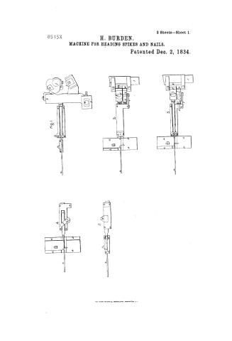
box separate and detached is to take it out to repair when it becomes worn by use. It will now be observed, that were a piece of iron or rod gripped fast by two dies, as described above (or two side steels, on the sides and wedges, above and below as described in my specification in the Patent office, dated the 26th day of May 1825) preparatory to being headed and the cast iron block forced forward so as to bring the steel box which is inserted in the end, frame in close contact with the dies, side steels & wedges, or any other substances or materials used for the purpose of gripping or holding the piece of iron or rod, while the head is being formed, while in this situation, were the header, which passes thru the cast iron block, and steel box forced forward by a cam, it would force that part of the iron or rod which projected beyond the dies &c. &c. intended for the head so as to fill the steel box, making the head, the precise shape of the box, as soon as the head is formed, the cast iron block, steel box and header are all drawn back from the head of the nail by a suitable cam for that purpose.
The dies, side steels, and wedges, or whatever is used for the purpose of gripping the nail or spike opening, and lets the nail or spike loose.
For a further illustration of the improvement, reference must be had to the annexed drawings and description thereof forming part of this specification.
Be it also known that I Henry Burdon as aforesaid hath invented a further improvement in the machine for making wrought nails or spikes as patented to him the twenty sixth day of May 1825, which is described as follows. What I then termed side steels, was two pieces of steel, each about three inches wide, one inch thick and the length of the nail intended placed parallel to each other and fastened by means of screw bolts in the moving frame, between these side steels the rod or piece of iron intended for the nail or spike, was confined, while it was headed and drawn to a point by the wedges, one of which was fastened in a roller under and the other above. The edges of these wedges, being precisely the thickness of the nail or spike intended, would lock between the side steels, while in the act of rolling out the nail. It is obvious that the side steels must press close and hard on the sides of the wedges, to prevent the iron from escaping between the side steels and wedges, while drawing or
Page 5.
rolling the point, which continual pressure & rubbing wore chaffed or wore both the side steels and wedges, so as to make their surfaces very rough, which occasioned a great deal of grinding and repairs. It occurred to me that the cause of this great wearing of the surfaces was occasioned by the parts being all of one and the same material, being all steel and that by making what I termed side steels of some other hard material, the difficulty might be obviated. I made many experiments with different metals, and found that common cast iron chilled on the edges, answered a very excellent purpose. The method of casting these side steels is as follows. I make a pattern of wood, the size intended for the side steel, then cast a piece or block of iron, having a mortice exactly the size of the edge of the side steel, and about one inch deep. The pattern is then inserted on its edge into the mortice of the cast iron block. The pattern being surrounded by common moulding sand, which after being extracted the iron is poured into the mould; one inch in depth being surrounded by cold iron chills and hardens the edge of the side steel as far up as is wanted, which being ground, is ready for use.
First. What I claim as my invention and improvement, is the method of forming the heads of nails or spikes in a steel box as above described. I would here also remark, that no matter whether the box be made of cast iron or other metal, whether in two or more pieces, whether formed of part of the die, &c. &c. so long as the chamber or the hole is so constructed as to admit the header to play tight and at the same time forcibly similar to the piston of a pump or Steam Engine. When spikes with round heads are wanted the box and headers resemble very much the Steam Engine piston & cylinder without the covers.
Secondly — I claim as my invention the use of cast iron side steels chilled on their edges as described above, in lieu of their being made of steel, as described in my specification now in the Patent Office, dated the 26th day of May 1825. I would also remark that my claim extends to what is commonly termed cast iron, no matter how it is hardened; although I prefer chilling it or hardening it in a cast iron block.
Witness, { G. Ford
John B. Mayson }
Henry Burden
(No. 2)
(No. 3)
(No. 4)
(No. 5)
(No. 6)
(No. 7)
(No. 8)
(No. 9)
(No. 10)
(No. 11)
(No. 12)
(No. 13)
(No. 14)
(No. 15)
(No. 16)
(No. 17)
(No. 18)
(No. 19)
(No. 20)
(No. 21)
(No. 22)
(No. 23)
(No. 24)
(No. 25)
(No. 26)
(No. 27)
(No. 28)
(No. 29)
(No. 30)
(No. 31)
(No. 32)
(No. 33)
(No. 34)
(No. 35)
(No. 36)
(No. 37)
(No. 38)
(No. 39)
(No. 40)
(No. 41)
(No. 42)
(No. 43)
(No. 44)
(No. 45)
(No. 46)
(No. 47)
(No. 48)
(No. 49)
(No. 50)
(No. 51)
(No. 52)
(No. 53)
(No. 54)
(No. 55)
(No. 56)
(No. 57)
(No. 58)
(No. 59)
(No. 60)
(No. 61)
(No. 62)
(No. 63)
(No. 64)
(No. 65)
(No. 66)
(No. 67)
(No. 68)
(No. 69)
(No. 70)
(No. 71)
(No. 72)
(No. 73)
(No. 74)
(No. 75)
(No. 76)
(No. 77)
(No. 78)
(No. 79)
(No. 80)
(No. 81)
(No. 82)
(No. 83)
(No. 84)
(No. 85)
(No. 86)
(No. 87)
(No. 88)
(No. 89)
(No. 90)
(No. 91)
(No. 92)
(No. 93)
(No. 94)
(No. 95)
(No. 96)
(No. 97)
(No. 98)
(No. 99)
(No. 100)
Published accounts: journal notice
Notice in the monthly list of patents
Journal of the Franklin Institute, new ser., vol. 15 (1835), p. 143 · View the page
578. Nail and spike machine.-Henry Burden, Troy, New York,
Published accounts: journal notice
Notice in the monthly list of patents, with remarks
Journal of the Franklin Institute, new ser., vol. 16 (1835), p. 18 · View the page
8. For an improvement in the machinery for manufacturing Wrought Nails and Spikes; Henry Burden, Troy, Rensselaer county, New York, December 2.
Remarks. This patent is taken for improvements on a machine invented by Mr. Burden, and patented on the 26th of May, 1825. The improvements consist in the manner of forming and using the heading dies, a full explanation of which would require a reference to the description and drawing of the original machine. One of the improvements, it will be seen by the subjoined claims, consists in substituting chilled cast iron for steel, in a part of the dies, these having been found to wear longer, and being easily replaced. "What I claim as my invention, is the method of forming the heads of the nails, or spikes, in a steel box, as above described. I would here also remark, that, no matter whether the box be made of cast iron, or other metal, whether in two or more pieces, whether formed in part of the dies, &c. &c., so long as the chamber, or hole, is so constructed as to admit the header to play tight, and at the same time freely, similar to the piston of a pump, or steam engine. Secondly, I claim as my invention, the use of cast iron side steels, chilled on their edges, as described above, in lieu of their being made of steel, as described in my specification of May, 1825. My claim extends to what is commonly called cast iron, no matter how it is hardened, although I prefer chilling or hardening it in a cast iron block."
About this record
- Patentee
- Jim Shaw's X-patent list
- Date
- the Name and Date index of patents, USPTO records, Jim Shaw's X-patent list
- Invention
- the Name and Date index of patents
- Listed in
- the Name and Date index of patents, USPTO records, Jim Shaw's X-patent list, the Journal of the Franklin Institute, Burke's List of Patents (1847)
- The residence comes from the Franklin Institute's journal.
- Burke's 1847 Patent Office list gives the same patent.