

Drawings and documents
USPTO scan
The patent as scanned by the USPTO
-
 Page 1
-
 Page 2
-
 Page 3
-
 Page 4
-
 Page 5
-
 Page 6
-
 Page 7
-
 Page 8
-
 Page 9
-
 Page 10
-
 Page 11
-
 Page 12
-
 Page 13
-
 Page 14
-
 Page 15
-
 Page 16
-
 Page 17


U.S. Patent and Trademark Office · Google Patents
Show the transcription Hide (5,380 words)
Machine transcription (LightOnOCR) of the pages as scanned by the USPTO, most of them the handwritten copies made when the records were restored after the 1836 fire. Not checked; it can misread handwriting, so compare it with the scan.
Page 1.
8522½X
Armstrong & King
Grain Winnowers
Patented Dec. 1, 1834.
This part of drawing lost
Fig. 1
Fig. 2
Page 2.
12/2/1834 8522½X
Dec. 2, 1834 235
Martin, M. Armstrong & William H. King
Letters Patent
The Schedule referred to in these Letters Patent and making part of the same containing a description in the words of the said Martin M. Armstrong & William H. King themselves of their improvement in machinery for sifting, cleaning and screening grain and berries of all kinds. To all to whom these presents shall come —
Be it known that we Martin M. Armstrong & William H. King both of the City and County of New York and State of New York have jointly invented a new and useful improvement in machinery for sifting, cleaning and screening grain & berries of all kinds & descriptions whatsoever, be the same whole or ground and that the following is a full and exact description of the construction and operation of the said machinery as invented and improved by us the said Martin M. Armstrong & William H. King.
The Invention and Improvement aforesaid for the purposes aforesaid is two fold to set. In the first place the said invention & improvement embraces and consists of a cylindrical sifter formed & constructed in the manner following, that is to say: a cylinder is formed covered & bounded on its circular surface or boundary by (one or other, not with or not) of such strength construction and proportions as may be required by the particular kind or description of grain or berries to be sifted, cleaned, or screened. This cylinder is divided into two apartments by similar not works of like strength, construction and proportions placed & being in a cylindrical form, within and parallel to the said outer covering or boundary, and forming a smaller cylindrical apartment within the larger or outer apartment. The said not works is in both instances secured & strengthened by bars of iron or metal placed & being lengthways with the said cylinder and, at both ends firmly affixed and secured to rims or facings of wood or metal which protect the ends of
Drawing (See 2nd page)
Page 3.
12/2/1834 6522½ X
236.
es of the said network respectively & to which bars the said net-
work is secured. One extremity, or end of the said outer apart-
ment of the said cylinder is closed and bounded by a circular
end plate of wood or metal of the same diameter of the said
cylinder thereunto affixed and secured: from the middle of which
said end plate a circular piece is cut out of sufficient size or di-
mensions, to leave entirely open the end or extremity of the said inner
apartment of the said cylinder. The said end plate is strength-
ened guarded and secured by two arms of wood or metal crossing
each other at right angles at the centre of the said end plate:
where they are secured in a journal or bearing of wood or metal
and which arms run and extend at both ends thereof, respect-
ively to the circumference of the said end plate. Between
the said end plate and the said rim or felly which protects
the said inner edge of the said outer network as aforesaid
a narrow open space is left all around the said cylinder
except where the said bars pass from the said last named rim
or felly to the said end plate. The other extremity or end of
the said cylinder is open except so much thereof as is covered by
a narrow projecting rim of wood or metal which is affixed
and secured to the said rim or felly which protects that end
edge of the said outer network as aforesaid. The said project-
ing rim projects inwards from the said outer boundary of the
said cylinder and is sufficiently wide to prevent any grain or
seeds from passing or falling from the said outer apartment of the
said cylinder at that end thereof. Also short distance within the
said projecting rim two arms of wood or metal are placed
which arms cross each other at right angles at the centre of
a circle whose circumference is on the exterior surface of the
said cylinder and are there secured in a journal or bearing
of wood or metal and which arms at both ends thereof
respectively run and extend and are secured to the said
rim or felly, which at that end of the said cylinder, is
Page 4.
12/2/1834 8522 1/2 X
23
joints, the end edge, of the said, outer network, as aforesaid. The said inner apartment of the said cylinder is occupied by a fan composed of a shaft to which are affixed and secured at alternate right angles to each other four thin plates of wood or metal of such length and depth as will permit them to revolve with and upon the said shaft freely and with as much effect as may be within the said inner apartment of the said cylinder. The said cylinder is attached to, and supported by an oblong frame of wood or metal consisting of four legs, sufficiently secured together by single cross bars on each of the sides thereof and by double or parallel cross bars on each side of the ends thereof respectively; with this frame the said cylinder is joined connected & attached on the said open end of the said cylinder by a short solid round shaft of wood or metal which passes through and revolves freely within a sufficient bearing and journal in an inner cross bar on one end of the said frame and is firmly secured to the said journal or bearing of the said arm within that end of the said cylinder aforesaid; and on the other or close end of the said cylinder by a short round shaft which is firmly affixed and secured to the said journal or bearing of the said arms of that end of the said cylinder and which shaft passes through and freely revolves within a sufficient journal in an inner cross bar of that end of the said frame. Through the middle of the last named shaft is a round hole or bore of sufficient diameter to allow the said shaft of the said fan to work or revolve freely within it. Affixed and secured to the said frame as close as convenient above the said open end of the said cylinder is a sufficient hopper made of wood or metal to the bottom of which hopper is affixed & secured a brace or conductor of wood or metal which conducts and leads from the opening in the bottom of the said hopper and inclines gradually towards the said open end of the said cylinder.
Page 5.
12/2/1834 8522 ½X
238
The lower end of the said conductor or leader rests in the space between the aforesaid projecting rim (which prevents grain or berries from falling off at that end as aforesaid) and the said arms which are affixed to the said cylinder at a short distance within the said projecting rim as aforesaid, so that the said cylinder can revolve freely without being interrupted, stopped or touched by the said leader or conductor, and so also that grain or berries falling from the said conductor or leader fall upon & against the lower part of the inner surface of the said outer apartment & within the said projecting rim. The said legs of the said frame at that end thereof, where is the said open end of the said cylinder are as much longer than the said other legs thereof as is sufficient to incline the said cylinder from the said open end thereof to the said close end thereof in such a degree as will cause grain or berries when in the said outer apartment of the said cylinder to descend gradually with the motion of the said cylinder from the said open to the said close end of the said outer apartment thereof, & receiver is affixed and secured to the said frame under the said cylinder which receiver gradually inclines towards and terminates in a conductor or mouth or other opening.
Directly under the said narrow open space left as aforesaid round the said cylinder at the said close end thereof, is affixed and secured another smaller receiver wholly separate from the said first-mentioned receiver and descending and inclining to a point where it terminates in a leader or conductor which inclines towards and beyond that end of the said frame. Below the said two receivers and perpendicular to each other and parallel to the aforementioned short shafts of the said cylinder a shaft within the lower shaft passes through and connects freely within journals and bearings in the lower ends of
45
Page 6.
12/2/1834 8522'12X
23
of the said ends of the said frame, and to which lower shaft between the bearings thereof at each end of the said frame (as respectively) are affixed and secured two round pulleys of wood or metal of unequal diameters the smaller thereof being at that end of the said frame where is the said open end of the said cylinder and the larger thereof at that end of the said frame where is the said close end of the said cylinder. The proportion between the diameters of these lower pulleys must be regulated by the increased velocity which it is desired to impart to the said fan. The said cylinder is worked or set in motion by a crank (or other power, which may be applied) attached to the said short solid shaft of the said cylinder or such power may be applied to the said other short shaft of the said cylinder or to the said lower shaft.
To the said short solid shaft of the said cylinder between the bearings thereof in the said double or parallel crags has a round pulley of wood or metal is affixed and secured directly over the said smaller pulley of the said lower shaft and is as much longer in diameter than the last named pulley as the increased velocity desired to be given to the said fan may require. The said upper pulley is connected with and acts upon the said smaller pulley of the said lower shaft by means of a connecting strap which when the crank (or other power aforesaid) turns the said upper pulley, will upon it turns the said lower pulley in the same direction, and with as much greater velocity as the difference between the circumferences of the said pulleys will cause. On the other end of the said lower shaft, the said larger pulley thereof of fixed necessity revolves with the same velocity as the said smaller pulley last described, and by means of a connecting strap is connected with and acts upon a smaller pulley affixed and secured to the said shaft of the said fan (which)
Page 7.
240
directly above the said larger pulley of the said lower shaft, the difference in diameter between the said two last-named pulleys must also be regulated by the increased velocity which it is desired to impart to the said fans.
The said shaft of the said fan is set in motion by and revolves within the said pulley thereunto affixed as above mentioned and passes out through and revolves within the afore-mentioned box in the said short shaft of the said cylinder at that end thereof having its own journal and bearing on an outer cross bar at that end of the said frame and at its opposite extremity rests upon and revolves freely within a bearing in the inner end of the said short solid shaft, which there supports the said cylinder and connects it with the said frame as aforesaid. The said connecting strap last aforementioned is engaged between the said pulleys which it connects as aforesaid so that thereby the motion given to the said fan is opposite to the motion given to the said cylinder as aforesaid, the revolutions of the said fan being directly reverse to those of the said cylinder. The said fan moves with as much greater velocity than the said cylinder as the respective differences between the diameters of the said pulleys will cause as aforesaid. The motions aforesaid may also be obtained by connecting rods or cog-wheels used in the place and stead of the aforesaid pulleys and connecting straps or by connecting the said cylinder with a pulley on the said lower shaft by means of a connecting strap or connecting rod. Grain or berries being placed on the said hopper pass then the said ladder or construction there to support, and fall in aforesaid against and upon the said inner surface of the said outer not-work of the said outer apart ment of the said cylinder. They are prevented from falling from or passing out of the said open end of the said outer apart ment by the aforementioned projecting rim. The said cylinder
12/2/1834 8522½X
Page 8.
cylinders being put in rapid motion in manner aforesaid the said grain or berries are necessarily kept in rapid and continuous motion against and upon the said fan since surface of the said outer network of the said cylinders and the said fan at the same time revolving in the opposite direction with much greater velocity forces and throws a strong current of air against the said grain or berries and continually in a manner opposes and resists the motion given to them by the said cylinders. By this means the said grain or berries are speedily sifted, cleaned and screened of & from all impurities sufficiently small to pass through the openings in the said outer network whence the said impurities fall into the said larger receiver & pass off and are discharged at the said mouth or outer opening thereof and the said grain or berries gradually passing down the inclined inner surface of the said outer network to the close end of the said outer apartment, fall through the aforementioned narrow open space then left round the said cylinders as aforesaid into the said smaller receiver below and under the same as aforesaid whence they pass off by & through the said leader or conductor thence leading or conducting as aforesaid. When such grain & berries so to be sifted cleaned and screened are heated the aforementioned rapid motion of the said cylinders and the said current of air so thrown against the said grain and berries as aforesaid speedily cool the same, and when such grain and berries are ground & have become caked or hardened by wet or otherwise the said motion and air speedily break such cakes & reduce such hardings and restore such grain and berries to their proper state as ground grain & berries. A moveable case or covering may be placed over the said cylinders for the purpose of preserving and securing the same from dust &c or noxious air. We, the said Martin A. Armstrong & William W. King say and claim that we are the joint and original inventors of the cylinders herein before mentioned & described for the purposes herein
Page 9.
12/2/1834 8522½X
242
herein before mentioned and described, and of the application of said as herein before stated and set forth of all the machinery herein before mentioned and described for the purposes aforesaid.
In the second place the said invention & improvement embraces & consists of a separator made of wood or metal and which is of the usual form of a sieve, except that the bottom thereof may be either solid or perforated like that of a sieve or have the outer part thereof perforated like a sieve and the inner or middle part thereof solid and except also the openings or passages therefrom herein after particularly mentioned and described. In the projecting rim of the said separator and on a level with the bottom thereof or in the bottom plate of the said separator and close to the said projecting rim thereof are one or more openings continued by leads or conductors on the outside of the said separator into which leads or conductors fit small slides which close or lessen the passages thereof respectively at pleasure. The number of the said last named openings must be regulated by the size and capacity of the separator used. There is also another opening in the middle of the said bottom plate, which opening is circular, the center thereof being the centre of the said bottom plate. To the last named opening both above and below fits loosely a thin plate of wood or metal of greater diameter than the said opening and each of which plates has a smaller opening or passage in the middle thereof respectively also circular. These last named openings or passages are connected together by a hollowed or bored piece or pipe of wood or metal passing through the said opening in the middle of the said bottom plate and opening to the said openings in the said thin plates so that one thereof fits loosely but closely above or on and the other thereof fits loosely but closely below or under the said bottom plate of the said separator and so as to cover the said opening in the said bottom plate last aforesaid, except
Page 10.
except so much thereof as is equal to one occupied by the passage in the said hollowed or bored piece or pipe. The said hollowed or bored piece or pipe rises above the bottom of the said separator to a small height more or less, as may be required by the size or capacity of the separator to which it is attached and of which it forms a part and of the shape and form of a common funnel the inverted conical part or mouth thereof being above and the pipe thereof being as aforesaid below the level of the bottom of the said separator. The said separator rests or stands so as to be removed at pleasure upon three equal cranks placed and being in a frame of wood or metal and at the respective corners of an equilateral triangle; these last named cranks stand or rest in steps or bearings in the lower part or platform of the said frame last named, wherein the lower ends thereof work or revolve freely. The shafts of the said three cranks work or rotate freely in sufficient journals in the said frame and the said three shafts work freely in equidistant journals in the said bottom plate of the said separator. The said three cranks may be constructed so that their sweeps may be lengthened or reduced by means of a slot-way and movable pin in each of the arms thereof respectively; the sweeps of the said three cranks must be so regulated that the eccentricity of the aforementioned levers or connectors from the said smaller receiver below and under the narrow open space round the said cylinder as aforesaid shall always during the motion of the said separator herein after described ever some point of or on the said bottom plate of the said separator between the said projecting pins thereof and the said movable centre piece thereof herein before mentioned and described. The said frame of the said separator is affixed and secured to the said frame of the said cylinder at the close end thereof under the said inclined levers or connectors which project from the said smaller receiver beyond that end of the said cylinder and frames as
Page 11.
244.
as aforesaid. On the supporting cranks of the said separator and to the shaft thereof is affixed and secured a suitable cog wheel corresponding to and joining and connected and locked with another suitable cog wheel affixed and secured to that end of the said lower shaft without and beyond the bearings thereof. Thus when the said lower shaft is in motion as aforesaid, the last named cog wheel thereunto attached sets in motion the corresponding cog wheel on the said supporting cranks of the said separator as aforesaid; and the said last-named cranks thus set in revolution propel and force the said separator so that a point at the centre of the said bottom plate thereof performs a circle round a point equidistant from the said corners of the said equilateral triangle with a radius equal to each of the arms of the said supporting cranks; and when the said separator is put in motion as aforesaid the said movable centre piece thereof aforesaid is continually thrown towards that point on the edge of the said bottom plate of the said separator farther from the said point, equidistant as aforesaid from the said corners of the said equilateral triangle.
When grain or berries pass from the said inclined conveyer or leader connecting or leading from the said smaller receiver as aforesaid, they fall upon the bottom plate of the said separator between the said projecting rim thereof and the said movable centre piece thereof. By the laws of centrifugal motion, one of gravity, grain or berries being of greater specific gravity than impurities, impurities will then be thrown by the aforesaid motion of the said separator towards or against the said projecting rim thereof, whence they gradually pass off and are discharged through a passage or passages and leader or conveyor or leaders or connected in or close to the said projecting rim as aforesaid. The impurities being with grain or berries being of less specific gravity than the said grain or berries as aforesaid.
Page 12.
gradually accumulate around the said movable center piece, pass over and into the mouth thereof, as aforesaid and fall and are discharged through the said movable center piece as aforesaid.
Whatever tendency (if any) grain or berries might have on first falling on the said separator to pass to or into the said passage of the said movable center piece, is sufficiently resisted by the raised side of the said funnel or center piece until such grain or berries are thrown as aforesaid (towards or against) the said projecting rim of the said separator.
When grain or berries happen to be of less specific gravity than impurities mixed with them the operation of the said separator is necessarily reverse to the operation thereof herein before described: the said grain or berries gradually passing off through the said center piece and the said impurities through the said passage or passages in or close to the said projecting rim as aforesaid, and when grain or berries happen to be of less specific gravity than certain impurities mixed with them and of greater specific gravity than certain other impurities also mixed with them, then the said impurities are separated from said grain or berries, by passing the said grain and berries twice through the said separator as aforesaid by the means aforesaid. As particles of matter in or on the said separator near the said funnel or center piece are kept by the aforesaid motion of the said separator in continual motion around the center of the said bottom plate of the said separator, the said funnel or center piece is constructed and placed as aforesaid so as to receive or take a similar or corresponding motion as aforesaid, and thus the said motion of the said particles is not broken, interrupted or disturbed by the said funnel or center piece. That the said funnel or center piece may also be constructed and placed stationary and fixed at the center of the said bottom plate of the said separator and with this also upon the
Page 13.
the purposes aforesaid. If the said bottom plate or part thereof is perforated or made of net or sieve such as aforesaid any small dirt or impurity which may not pass away otherwise as aforesaid, will escape and be discharged through such net or sieve works or perforations. Thus dirt or other impurities which pass or escape with grain or berries from the said cylinder is separated therefrom by the aforesaid operation of the said separator. The aforesaid motion of the said separator may also be obtained by means of a connecting shaft connecting a round pulley affixed and secured to one of the said three supporting cranks of the said separator and a pulley affixed and secured to the lower of the shafts aforesaid or by means of a connecting rod, one extremity of which should be affixed to the said separator, and the other extremity to a crank or pulley affixed and secured to one of the shafts aforesaid; whereby the last named extremity of the said connecting rod would be carried round by the said crank or pulley describing a circle or an imaginary perpendicular plane, and the other extremity thereof would describe a circle or an imaginary horizontal plane, carrying with it the said separator. When desirable, two, three or more separators may be used in the manner following. To wit, to the shafts of two of the said supporting cranks (to which is not attached the said pulley or other pulley for the purposes aforesaid) round pulleys may be affixed and secured, connected by connecting shafts with similar pulleys similarly affixed and secured to a supporting crank of each of two similar separators respectively, and these additional separators may in like manner be connected with other similar separators. In this last named case of having more than one separator as aforesaid the said leader or conductor, leading or conducting as aforesaid from the said smaller receiver should branch off in as many separate branches as separators used, and such branches
Page 14.
ches should conduct grain or burrs equally to such separators in like manner as is herein before mentioned. Set forth and described; the said separator may be covered by a movable plate or cover with a sufficient passage for grain and burrs.
And we the said Martin & Armstrong & William H. Stying, do say and claim that we are the joint and original inventors of the said entire piece of the said separator as is herein before particularly described for the purposes of said and of the application and use of as herein before stated and set forth of the machinery herein before in the second place mentioned and described for the purposes of said. The said cylindrical sifters and the said separator may also be respectively used in the manner of said for the purposes of said separately and apart. And we the said Martin & Armstrong & William H. Stying have hereto annexed two views or drawings of the machinery invention & improvement herein before mentioned and described, as and for a part and parcel of this our specification.
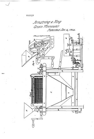
Thereof: one of the views or drawings marked No. 1 (number one) being a front or full view of the side of the said cylinder, separator and other machinery; and the other of the said views or drawings marked No. 2 (number two) being an oblique view or drawing of the open end or extremity of the said cylinder. And we the said Martin & Armstrong & William H. Stying, have thereunto respectively and to the several parts thereof respectively annexed certain letters as and for letters or marks of reference to represent or indicate the several and respective parts of the said views or drawings to which they are so annexed in the following, explanation of the said views or drawings to wit: A represents or indicates the hopper of said. B represents or indicates the feeder or conductor thereof leading or conducting as of said. C represents or indicates the
Page 15.
12/2/1834 8522½x
248.
wire or other net-work or boundary aforesaid of the said outer apartment of the cylinder aforesaid D. represents or indicates the aforesaid bars to which the last-named net-work is secured as aforesaid. E. represents or indicates the rims or fells which protect the end edges of the net-work within described respectively as aforesaid. F. represents or indicates the arms aforesaid coping each other at right angles at or near the respective ends of the said cylinder as aforesaid. G. represents or indicates the journals or bearings in which the said arms are secured as aforesaid. H. represents or indicates the wire or other net-work or boundary of the aforesaid inner apartment of the said cylinder I. represents or indicates the fan aforesaid. K. represents or indicates the aforesaid shaft of the said fan. L. represents or indicates the aforesaid short shaft of the said cylinder placed and being at the close end thereof as hereinbefore described M. represents or indicates the aforesaid narrow open space left all round the said cylinder at the close end thereof as herein before described N. represents or indicates the aforesaid bars to which is secured the said net-work of the said inner apartment of the said cylinder as aforesaid. O. represents or indicates the aforesaid crank attached to the said short solid shaft of the said cylinder as aforesaid P. represents or indicates the aforesaid short solid shaft of the said cylinder placed and being at the open end thereof as herein before described. Q. represents or indicates the aforesaid cross bars of the frame aforesaid to which the said cylinder is attached as aforesaid. R. represents or indicates the aforesaid legs of the said frame. S. represents or indicates the aforesaid pulley affixed and secured to the said short solid shaft of the said cylinder between the bearings thereof as herein before described. T. represents or indicates the aforesaid short solid shaft of the said lower shaft. U. represents or indicates the aforesaid cage.
Page 16.
12/2/1834 8522/2X
249
larger pulley of the said lower shaft. V represents or indicates the aforesaid pulley affixed and secured to the said shaft of the said fan as aforesaid. W. represents or indicates the aforesaid connecting strap which connects the said pulley of the said short solid shaft with the said smaller pulley of the said lower shaft as aforesaid. X. represents or indicates the aforesaid connecting strap which connects the said larger pulley of the said lower shaft with the said pulley affixed and secured to the said shaft of the said fan as aforesaid. Y. represents or indicates the aforesaid larger receiver placed and being under the said cylinder as aforesaid. Z. represents or indicates the aforesaid mouth or opening thereof. a. represents or indicates the aforesaid smaller receiver placed and being under the said narrow open space at the close end of the said cylinder as aforesaid. b. represents or indicates the aforesaid leader or conductor thence leading or conducting as aforesaid. c. represents or indicates the aforesaid lower shaft. d. represents or indicates the aforesaid projecting arm of the said separator. e. represents or indicates one of the aforesaid leaders or conductors leading or conducting from one of the aforesaid openings or passages in or close to the said projecting arm as aforesaid. f. represents or indicates the small slide which closes or opens the passage of the said leader or conductor as aforesaid. g. represents or indicates the aforesaid movable funnel, container or passage of the said separator. h. represents or indicates the aforesaid supporting cranks of the said separator. i. represents the aforesaid mitred cog-wheel affixed to the end of the said lower shaft as aforesaid. j. represents or indicates the aforesaid corresponding mitred cog-wheel affixed to one of the said supporting cranks as aforesaid. k. represents or indicates the aforesaid round pulley which may be affixed as aforesaid to one of the said supporting cranks of the said separator for the purposes
Page 17.
12/2/1834 8522½X
250.
purposes aforesaid. L. represents or indicates the connecting strap connecting the last named fully with another fully as aforesaid for the purposes aforesaid. M. represents or indicates the aforesaid frame of the said separator. N. represents or indicates the aforesaid narrow projecting rim projecting inwards around the said open end of the said cylinder as aforesaid.
Witnesses
E. C. Boyan
Elisha Morill
Martin S. Armstrong
Wm. H. King
Drawing
5360000
Published accounts: journal notice
Notice in the monthly list of patents
Journal of the Franklin Institute, new ser., vol. 15 (1835), p. 143 · View the page
574. Cleaning grain, &c.-M. N. Armstrong and Wm. R. King, N. Y. city,
Published accounts: journal notice
Notice in the monthly list of patents, with remarks
Journal of the Franklin Institute, new ser., vol. 16 (1835), p. 16 · View the page
This is an invention dedicated to Cloacina, a goddess to whom temples are erected even in christian lands, but whose rites are generally performed in secret, and alone. Whether or not the patentee has really improved upon the Parisian mode of conducting them, is a question the discussion of which we shall postpone, and that probably sine die. 4. For machinery for Sifting and Cleaning Grain, &c.; Martin N. Armstrong, and William H. King, city of New York, December 2.
Remarks. Were all the specifications in the Patent Office drawn up in the style of that before us, we should be compelled either to relinquish the task of examining their contents, or of purchasing a right to some literary winnowing machine, which would separate a grain of wheat from a bushel of chaff, if any such there be. We have conned over the eighteen pages of the aforesaid specification, and are still unable to tell what is said upon the subject; but we have learnt that the said machine consists of a cylindrical screen, and certain other contrivances for effecting the proposed object. The cylindrical screen, placed like a bolter, is double, containing one wire work cylinder within another, and within the inner cylinder a fan, furnished with four wings, or vanes, the shaft of which is in the axis of the two cylinders, and which fan is to revolve in a direction the reverse of that of the cylinders. The grain, or berries, &c. &c. operated upon, are, after being subjected to the action of this screen, to pass into a riddle, or vibrating box, worked by cranks, where the heavier and lighter bodies are to be separated from each other by a centrifugal, combined with a vibratory, motion. There are separate claims made to the respective parts of the apparatus which are brought successively into operation, but we have spent so much time in gleaning a few scattered ideas from the "full, clear, and exact" description, that we have none to spare for epitomizing, and examining into the validity of the claims made.
About this record
- Patentee
- the Journal of the Franklin Institute, Journal
- Date
- the Name and Date index of patents, USPTO records, Jim Shaw's X-patent list
- Invention
- the Name and Date index of patents
- Listed in
- the Name and Date index of patents, USPTO records, Jim Shaw's X-patent list, the Journal of the Franklin Institute, Burke's List of Patents (1847)
- The patentee's full name comes from the Franklin Institute's journal.
- Burke's 1847 Patent Office list gives the same patent.