

Drawings and documents
National Archives restored drawings: drawing
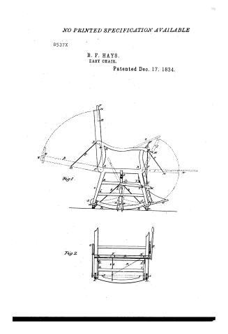
Benjamin F. Hays' Patent Drawing for an Easy Chair

National Archives, Restored Patent Drawings (Record Group 241) · Full-size scan at the National Archives · Catalog record
Show the text on the drawing Hide (42 words)
Words on the drawing as machine-read by the National Archives; not checked. Useful mainly for searching.
45. [62] FURNITURE. Rocking Chairz told Chairs / Benjamin of Hays / CLASSIFICA / 8537-t / EASY CHAIR. / DIVISION. / PATENTED 177 DEC 1834.V / Is / Fig.1. / MI / OIR / Fig.2. / fil / El / bb / Li / Is
USPTO scan
The patent as scanned by the USPTO
-
 Page 1
-
 Page 2
-
 Page 3
-
 Page 4
-
 Page 5


U.S. Patent and Trademark Office · Google Patents
Show the transcription Hide (1,677 words)
Machine transcription (LightOnOCR) of the pages as scanned by the USPTO, most of them the handwritten copies made when the records were restored after the 1836 fire. Not checked; it can misread handwriting, so compare it with the scan.
Page 1.
NO PRINTED SPECIFICATION AVAILABLE
8537X
B. F. HAYS.
EASY CHAIR.
Patented Dec. 17, 1834.
Fig. 1

Fig. 2

Page 2.
Dec. 17, 1834
Benjamin J. Hays, of Pittsfield, Mass.
Letter Patent.
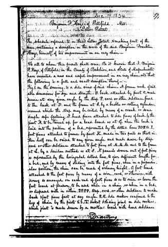
The schedule referred to in these Letters Patent, making part of the same, containing a description in the words of the said Benjamin Franklin Hays, himself, of his improvement in an easy chair.
To all to whom these presents shall come; Be it known that I, Benjamin J. Hays, of Pittsfield, in the County of Berkshire, and State of Massachusetts, have invented a new and useful improvement in an easy chair, and that the following is a full and exact description thereof.
Fig. 1. on the drawing, is a side view of said chair—A. frame work of suitable dimensions for size and strength. B. back attached by pivot C, made secure at any given angle by the strap P, cord or other substance fixed to the back at D, and the frame at E, by a buckle or rolling cylinder, around which the strap may be coiled by means of a crank, or some simple safe fastening. F. head piece attached to side pieces of back by the pivot H, to be turned up for a head board as at G, when the back is laid into the position of a bed, represented by the dotted lines BDH G, I. J. foot pieces attached to frame by pivot K, made in two parts so that either half can be raised to any given angle and made secure by strap cord or other substance attached to foot pieces at M, M, M, and to the frame at L, by a similar method as at E. N. panels drawn out of foot pieces, as represented by the horizontal dotted lines, to give sufficient length for a bed, and by means of sliding into the foot pieces, when in a perpendicular position, the chain can be made of ordinary height. O. foot board attached to the foot pieces by means of a wire, cord, or otherwise, with screws so arranged on each end of foot pieces so as to raise or lower the foot board at pleasure, to be used while in a chair, or when in a bed, or disposed with in either. P.P.P.P. strap, cord, or other substance to make back & foot pieces fast at any angle. R.R. side rockers confined to the legs of chair by the pivots S.S., T. socket sliding joint in side rockers, which joint is made secure by a mortise boxed with hard substance.
Drawing
Page 3.
in the end of each of the rockers R.R. where they meet in the socket T, and slide on the friction rollers V.V; or the same result may be produced by having the sliding mortice operate on the pivots S.S. WW, rivets fastening the socket T, to a piece of wood or metal joined to the short arm of the lever U, by a pin making a joint at X. V. lever attached to an arbor extending cross-wise and fixed to the frame by means of staples or otherwise; to the opposite end of which arbor, on the opposite side of the frame is fixed another short arm of the lever V, to which is attached a pitman or compound arm, socket, and rockers exactly corresponding with RR VV.T.WW.X.V. The lever V being detached from the frame to which it is made fast at Y by means of a staple V spiral or common spring is drawn upward and backward the rockers RR, at the same time sliding into the socket T, until the lever pitman and side rockers occupy the position defined by the dotted lines, or the pitman may be raised perpendicularly by cogs meshing into a wheel on the short arm of lever V, leaving the chain resting upon the cogs rockers a a, which are made fast by the rods bb, one end of each of which is made fast by a staple to the cogs rockers at a a, the other end of each made fast by a staple to a sliding bar, represented by a dotted line in the frame at C, and attached to the arbor on which it slides by staples or a hole passing thro' the box horizontally corresponding with the size of the arbor, to which sliding bar is attached the strap q, cord or other substance, sufficiently strong to move the bar back and forth, on the arbor in a horizontal direction—by which motion the cogs rockers a a, are folded into a horizontal position by turning on the pivots SS, or prefed out to a perpendicular position as at a a, d d, rollers (or castors) attached to frame pivot SS, forming a check to either pair of rockers, preventing the chain or from overturning and when both pair of rockers are withdrawn from a ro ing position, forming wheels on which the whole can be moved at pleasure in any direction, c, breast board attached to arm pieces by a hook and staple be elevated at pleasure forming an eating, working writing, or sleeping to Fig. 2, showing a front or rear view of chair. A, arbor attached to frame by staples or otherwise. B, long arm of lever outside of chair. C, C, short a of lever attached to arbor A, at XX, directly over the pitman. Z Z, on
Page 4.
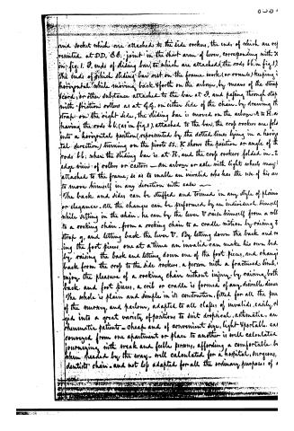
and socket which are attached to the side rockers, the ends of which are represented at D.D. & E. joint in the short arm of lever, corresponding with X in fig. 1. F. ends of sliding bar, to which are attached the rods b.b. in fig. 1. The ends of which sliding bar rest on the frame work (or rounds) keeping it horizontal while moving back & forth on the arbor, by means of the strap & cord, or other substance attached to the bar at F. and passing through strap with friction rollers as at G.G. on either side of the chain. By drawing the strap on the right side, the sliding bar is moved on the arbor A to H. as having the rods b.b. (as in fig. 1) attached to the bar, the cross rockers are folded into a horizontal position (represented by the dotted lines) lying in a horizontal direction) turning on the pivots S.S. K shows the position or angle of the rods b.b. when the sliding bar is at H, and the cross rockers folded in. I edge view of rollers or castors — an arbor or axle with light wheels may be attached to the frame, so as to enable an invalid who has the use of his arm to move himself in any direction with ease —
The back and sides can be stuffed and trimmed in any style of plain or elegance. All the changes can be performed by an individual himself while sitting in the chair. he can by the lever V raise himself from a roll to a rocking chair. from a rocking chair to a cradle motion by raising the strap g, and letting back the lever V. By letting down the back and raising the foot pieces one at a time an invalid can make his own bed by raising the back and letting down one of the foot pieces, and changing back from the cross to the side rockers. a person with a fractured limb, enjoy the pleasure of a rocking chair without injury. by raising both back and foot pieces, a crib or cradle is formed of any desirable dimensions. The whole is plain and simple in its construction, fitted for all the purposes of the nursery and parlour, adapted to all classes of invalids, easily changed into a great variety of positions to suit dropical, asthmatic, arthritic patients — cheap and of convenient size, light & portable, can be conveyed from one apartment or place to another is well calculated for journeying with weak and feeble persons, affording a comfortable bed when needed by the way. well calculated for a hospital, surgeons, dentist’s chair. and not less adapted for all the ordinary purposes of
Page 5.
common rocking chair, or a single bed, in a private family or public office.
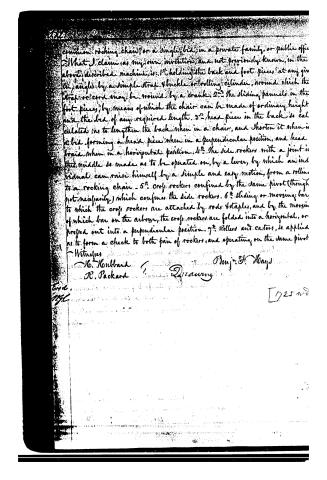
What I claim as my own invention, and not previously known, in the above described machine, is: 1st. holding the back and foot pieces at any given angle by a simple strap, buckle, or rolling cylinder, around which the strap or cord may be wound by a crank. 2nd. The sliding panels in the foot pieces, by means of which the chair can be made of ordinary height and the bed of any required length. 3rd. head piece in the back is calculated as to lengthen the back when in a chair, and shorten it when in a bed, forming a head piece when in a perpendicular position, and head board when in a horizontal position. 4th. The side rockers with a joint in the middle so made as to be operated on, by a lever, by which an individual can raise himself by a simple and easy motion, from a rolling to a rocking chair. 5th. cross rockers, confined by the same pivot (though not necessarily) which confines the side rockers. 6th. Sliding or moving bar to which the cross rockers are attached by rods, staples, and by the moving of which bar in the arbor, the cross rockers are folded into a horizontal, or pressed out into a perpendicular position. 7th. Rollers and castors, so applied as to form a check to both pair of rockers, and operating on the same pivot.
Witnesses
H. Hubbard
R. Packard
Benj. H. Hayes
D. 25 Nov
Published accounts: journal notice
Notice in the monthly list of patents
Journal of the Franklin Institute, new ser., vol. 15 (1835), p. 143 · View the page
590. Easy chair.-B. F. Hays, Pittsfield, Massachusetts,
Published accounts: journal notice
Notice in the monthly list of patents, with remarks
Journal of the Franklin Institute, new ser., vol. 16 (1835), p. 22 · View the page
20. For an Easy Chair; Benjamin Franklin Hays, Pittsfield, Berkshire county, Massachusetts, December 17.
Remarks. There are in this chair a number of ingeniously devised contrivances for moving, shifting, and adapting its various parts, so as to contribute to the relief of invalids, and render it useful for other purposes; to these parts there are numerous references, which would be useless without the drawing; all we can do, therefore, is to give the claim, which will make the general intention of the contrivance known. "What I claim as my invention, and not previously known in the above described machine, is, 1st. Holding the back and foot pieces at any given angle, by a simple strap and buckle, or rolling cylinder, around which the strap, or cord, may be wound by a crank. 2d. The sliding pannels in the foot pieces, by means of which the chair can be made of ordinary height, and the bed of any required length. 3d. Head piece in the back, so calculated as to lengthen the back when in a chair, and shorten it when in a bed, forming a head piece when in a perpendicular position, and a head board when in a horizontal position. 4th. The side rockers with a joint in the middle, so made as to be operated on by a lever, by which an individual can raise himself by a simple and easy motion, from a rolling to a rocking chair. Cross rockers, confined by the same pivot (though not necessary) which confines the side rockers. 6th. Sliding or moving bar, to which the cross rockers are attached by rods and staples, and by the moving of which bar on the arbor, the cross rockers are folded into a horizontal, or pressed out into a perpendicular, position, 7th. Rollers, or casters, so applied as to form a check to both pair of rockers, and operating on the same pivot." The foregoing claims are undoubtedly sufficiently distinct and particular, if they are not too much so for the interest of the patentee; from the manner in which they are made, they would seem to confine him to the precise methods represented; and from their number, there is danger that some one or more of them may have previously been used, as there is a host of similar invalid chairs here and in Europe.
About this record
- Patentee
- the Journal of the Franklin Institute, Journal
- Date
- the Name and Date index of patents, USPTO records, Jim Shaw's X-patent list
- Invention
- the Name and Date index of patents
- Listed in
- the Name and Date index of patents, USPTO records, Jim Shaw's X-patent list, the Journal of the Franklin Institute, Burke's List of Patents (1847)
- The patentee's full name comes from the Franklin Institute's journal.
- Burke's 1847 Patent Office list gives the same patent.