

Drawings and documents
National Archives restored drawings: drawing
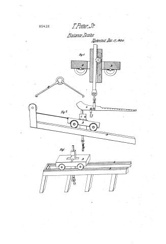
Thomas Potter, Sr.'s Patent Drawing for a Machine for Moving Weights

National Archives, Restored Patent Drawings (Record Group 241) · Full-size scan at the National Archives · Catalog record
Show the text on the drawing Hide (83 words)
Words on the drawing as machine-read by the National Archives; not checked. Useful mainly for searching.
73. MEASURING INSTRUMENTS. / [132] Balances. / Thomas Potter Jen" / Vol. / 3- / Moving Weights, Sgc! / Pistented / CLASSIFICATION / 8543+ / DI TSION. / Fid.3, / do / C' / Fife2, / do / Fif.1. / References, / Fif 1, horizontal ways camage, / Fifa, included / Fight, section of caniage & jack, / A A ways. Bcancage, c.jack. / D.steelyards, Engrapples." / Parem oth / Decr / Made underthe direction of the Commipron / Patents in conformity with the Act of 3rd / Ha Sumorth / Commissioner of Patents
USPTO scan
The patent as scanned by the USPTO
-
 Page 1
-
 Page 2
-
 Page 3
-
 Page 4


U.S. Patent and Trademark Office · Google Patents
Show the transcription Hide (1,266 words)
Machine transcription (LightOnOCR) of the pages as scanned by the USPTO, most of them the handwritten copies made when the records were restored after the 1836 fire. Not checked; it can misread handwriting, so compare it with the scan.
Page 1.
8543X
T. Potter, Sr.
Balance Scales.
Patented Dec. 17, 1834.
Fig. 1
Fig. 2
Fig. 1
Fig. 2
Page 2.
15 Dec 17, 1834 199.
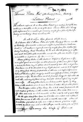
Thomas Potter Senr. of the County of Warren, Kentucky,
Letters Patent. 85437
The schedule referred to in these Letters Patent and making part of the same containing a description in the words of the said Thomas Potter Senr. himself of his improvement in a machine for removing weights from place to place & for loading and unloading Boats warehouses &c.
To all to whom these presents shall come;
Be it known that I Thomas Potter Senr. of the County of Warren and State of Kentucky, have invented a new and useful improvement in Mechanism to wit: A machine or engine for removing weights from place to place & for loading & unloading Boats Warehouses &c. &c. and that the following is a full and exact description of the construction and operation of the said Machine or engine as invented or improved by me,
Beams of strong timber or other material 55 feet in length, more or less, and a foot square more or less, are to be procured. If 55 or more feet in length is desired, the timber may be spliced so as to consist of more than a single beam. These beams are to be elevated to any height desired, and are to be supported by strong posts, standing perpendicular or otherwise, and sufficiently numerous to prevent the beams from swaying and the rows of posts at bottom, to be 8 feet apart, more or less, the two beams are to be precisely horizontal & parallel with each other, and may be placed at any desirable distance apart, say one foot more or less. The ends of these beams, are to be connected together by strong timber or other material, so as to cause the beams to retain their parallel position.
From the upper outside of these beams, there is to be nailed perpendicular side rails composed of timber or other suitable material, three inches thick, more or less, these side rails are to be connected at their ends by rails of equal length.
On the upper sides of these beams, are to be laid iron or steel rails or plates to extend from one end to the other, two inches in breadth, more or less. A Car is to be constructed of 4 wheels 10 inches, more or less in diameter of cast iron or other suitable material and with or without flanges, and the wheels of the one to be
Drawing See Class of Balances
Page 3.
suitable wreaths to run on the rails or plates aforesaid. If the wheels are made without flanges, then the car is to be kept to its proper place and made to run on the rails or plates by means of horizontal friction wheels placed in the car, so that their periphery will just bear against the side rails which must be of such height as will allow the friction wheels of the car to come in contact with them.
The axletrees of the cars are to be of iron or other suitable material 2 inches in diameter, more or less, and are to be set into a block 6 feet in length, more or less and 2½ feet wide, more or less, into which block mortises are made to let the wheels revolve freely around the axletrees according to the model herewith sent, then the center of this block which constitutes the car, a hole is to be morticed 18 inches in length more or less, 8 wide more or less, on the top of the block suitable notches on each side of the mortises are to be cut, for the elevator to rest in. The elevator is an instrument made like a common jack screw the bar of which is to be ten feet long, more or less, and is to pass down through the hole morticed in the center of the block, and then the opening left between the parallel beams. At the end of the bar there is to be a device to which a scale or grapples is attached, so that the scale may be turned around as convenience may dictate. The scale or grapples in lieu of the scale is to receive the weight intended to be moved, whatever it may be. It is then to be raised by turning the lever which work the elevating bar, and then carried to the place desired by moving the car on the rails. The weight to be moved is to swing below the car and rails.
Instead of an elevator constructed upon the principle of the jack screw if found to be more convenient, a system of pulleys may be used by attaching them to the car, or in place of the pulleys, the wheel and axle or windlass may be used, and whether the one or the other is used the weight is to be elevated so as to swing under the car and rails and then to be moved to the place desired, by moving the car on the rails. The beams and rails thereon may not be horizontal and still they will, by means of the car to run on them as aforesaid, and the elevator be very useful in performing the same services which are contemplated to be performed when precisely horizontal. When the beams make an angle with the horizon, the car may be made to ascend by means of a windlass attached to either end of the beams.
Page 4.
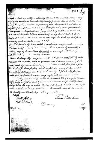
a rope or chain connecting or attaching the car to the windlass I design using the foregoing machine or engine for the following purposes, First—in loading or unloading boats, ships, and water craft of every kind, the model to be sent shows a projection of seven feet over each end of a boat from which it is apparent that a load of rock, or heavy material of any kind may be taken in at one end, put out at the other & placed conveniently in any part of the boat, such a boat and machine attached would be very useful in building small dams removing rock on water course, &c. &c.
Second—in transporting heavy articles of merchandise and produce from warehouses to markets and from markets to warehouses, this is to be done by constructing a stationary way by being placed horizontally or at an angle with the horizon on posts let into the ground as already described,
Third, In transporting heavy burdens of all kinds and descriptions, by erecting permanent or temporary ways as aforesaid, and to be used in removing rock, earth, wood, logs, minerals, and every conceivable article from place to place. The machine for these purposes will be useful in removing rock, and dirt from cellars, supplying saw mills with saw logs, & for all other purposes where it is desirable to remove heavy weights with ease and convenience.
My invention chiefly consists in the construction of a way for transporting heavy weights in such manner as to allow the weight transported to swing below the way on which the car is to move to which can the weight is to be attached as already described. The invention may be denominated the elevating and transporting rail way or engine.
Witnesses
Jos. R. Stiles
Jon. Gibson
Thomas Porter, Senior.
Drawing
Ex?
C. M. W.
1290 n.b.
Published accounts: journal notice
Notice in the monthly list of patents
Journal of the Franklin Institute, new ser., vol. 15 (1835), p. 143 · View the page
587. Removing weights, unloading boats, &c. -Thomas Potter, Bowling Green, Kentucky,
Published accounts: journal notice
Notice in the monthly list of patents (listed with a different spelling or date)
Journal of the Franklin Institute, new ser., vol. 16 (1835), p. 21 · View the page
For a Machine for Removing Weights, and Loading and Unloading Boats, &c.; Thomas Patten, Sr., Bowling Green, Warren county, Kentucky, December 17.
Published accounts: specification
Specification printed in the Journal of the Franklin Institute
Journal of the Franklin Institute, new ser., vol. 16 (1835), p. 40 · View the page
Text of the specification as printed in the Journal, from OCR; not proofread.
Specification of a Patent for a Furnace for Preparing and Smelting Iron Ore, with Anthracite Coal. Granted to THOMAS S. RIDGWAY, Pottsville, Schuylkill county, Pennsylvania, December 17th, 1834. The hearth of the smelting furnace, or stack, as seen in the section, letter J, may be in the usual form of smelting furnaces, and receive the blast at one or more openings in the bellows wall, made for the purpose, excepting the wind wall, opposite the blast, marked letter H, which is at an angle of forty-five degrees, or thereabout, and extending up the said wall of the stack to the bottom of a door, or opening, letter E, made for the purpose of rendering the fire manageable; this door will be placed in the stack at the top of the smelting fire, which will be from four to six feet high above the hearth, that being about the maximum height that a blast can be forced through anthracite coal; whereas the usual height to which it is forced in a charcoal furnace is thirty-five feet. Another stack, marked I, in the section, to be charged or loaded with anthracite coal, and kept hot by caloric received from the smelting stack by means of one or more openings in the wall of the smelting stack, opposite O, marked in the draft, at a convenient height BECK & JENKS' Machine for Hulling Clover. above the smelting fire, or by means of a separate fire, as the case may be; the intention of this operation is to dissipate sulphur from the coal, and to keep it in a proper state of heat for the smelting fire, without useless consumption of fuel. At the bottom of this stack is a door for the purpose of taking out the coal, after it is prepared to put on the smelting fire. K The purifying and carbonating stack, oven, or chest, marked K in the draft, may be attached to the smelting furnace, or be apart from it, and receive caloric, or heat, from the smelting furnace, by one or more apertures in the wall of the smelting stack, opposite the letter O in the draft, or by a separate fire. This stack is to be loaded or charged with iron ore and anthracite coal, or charcoal, or iron ore and charcoal, together with the proper fluxing materials, as may best prepare the ore before it is put on the smelting fire. There is a door in the bottom of this stack, for the purpose of taking out the ore after purification. This indispensable operation of carbonating the ore, cannot be performed without heat, in the absence of oxygen, nor can it be performed in the usual way, owing to the great specific gravity and slow combustion of anthracite coal; whereas, in this way, only a very small quantity of charcoal will be required to purify and carbonate a ton of ore. What I claim as my own invention is the carbonating stack, oven, or chest, and also the stack for preparing the anthracite coal, and relieving the smelting fire of the great burthen of ore and anthracite coal requisite in the usual way of smelting; also, the inclined wind wall, which renders the smelting fire so manageable that it may be stirred as often as required; and, lastly, the combination of the above three stacks. These may be built of stone, or any good, durable material, and of any convenient size or capacity, suitable to the power of the blast, with valves at the tunnel heads, or top, to regulate and direct the heat from one stack to another. THOMAS S. RIDGWAY.
About this record
- Patentee
- the Journal of the Franklin Institute, Journal
- Date
- the Name and Date index of patents, USPTO records, Jim Shaw's X-patent list
- Invention
- the Name and Date index of patents
- Listed in
- the Name and Date index of patents, USPTO records, Jim Shaw's X-patent list, the Journal of the Franklin Institute, the Journal of the Franklin Institute, Journal, Burke's List of Patents (1847)
- The patentee's full name comes from the Franklin Institute's journal.
- The residence comes from the Franklin Institute's journal.
- Also listed in a contemporary journal or list under a different spelling or date; the record shown follows the standard lists.
- Burke's 1847 Patent Office list gives the same patent.