

Drawings and documents
National Archives restored drawings: drawing
P.E. Daniels' Patent Drawing for a Planing Machine

National Archives, Restored Patent Drawings (Record Group 241) · Full-size scan at the National Archives · Catalog record
Show the text on the drawing Hide (38 words)
Words on the drawing as machine-read by the National Archives; not checked. Useful mainly for searching.
144. WOOD WORKING MACHINES. / Planers, Rotary Disk. / 83 / Pa Daniels Slaning Woo / 75 laner attactements Planing Machine / Patented 23 Dec: 1534. / COAS / 8548- X / ISI CIT / 20 / y10
USPTO scan
The patent as scanned by the USPTO
-
 Page 1
-
 Page 2
-
 Page 3
-
 Page 4
-
 Page 5


U.S. Patent and Trademark Office · Google Patents
Show the transcription Hide (1,272 words)
Machine transcription (LightOnOCR) of the pages as scanned by the USPTO, most of them the handwritten copies made when the records were restored after the 1836 fire. Not checked; it can misread handwriting, so compare it with the scan.
Page 1.
No Printed Specification Available
8548X
T. E. Daniels.
Wood Plane Attachment.
Patented Dec. 23, 1834.

A.M. PHOTO-LITHO. CO. N.Y. (OSBORNE'S PROCESS)
Page 2.
Dec. 26, 1834
Thomas C. Daniels
Letters Patent
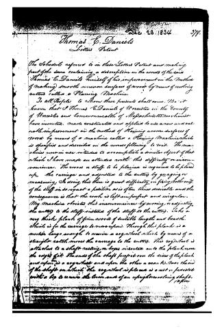
The Schedule referred to in these Letters Patent and making part of the same containing a description in the words of the said Thomas C. Daniels himself of his improvement in the method of making smooth uneven surfaces of wood by means of revolving cutters called a Planing Machine.
To all People to whom these presents shall come, We it known that I Thomas C. Daniels of Worcester in the County of Worcester and Commonwealth of Massachusetts machinist have invented, made construct and applied to use a new and valuable improvement in the method of Planing uneven surfaces of wood by means of a machine called a Planing Machine which is specified and described in the words following to wit. The machines now in use intended to accomplish a similar object of that which I have made are attended with this difficulty or inconvenience. The wood or stuff to be planed is required to be placed upon the carriage and adjusted to the cutters by gauging or measuring. In doing this there is great difficulty in fixing both ends of the stuff in so exact a position as is often times desirable and the consequence is that the work is left imperfect and irregular.
My machine obviates this inconvenience by moving or adjusting the cutter to the stuff instead of the stuff to the cutter. Take a very thick plank of join wood of suitable length and breadth. Which is for the carriage to move upon. Through this plank is a mortise large enough to receive a cog wheel which by means of a straight rack moves the carriage to the cutters. This cog wheel is attached to a shaft resting on boxes inserted into the plank near the edge of it. The ends of the shaft project over the sides of the plank and upon is a cog wheel and upon the other a crank to turn the end of the shaft on which the cog wheel is placed is a rest or pedestal with a lip to receive the lower end of an upright revolving shaft.
Page 3.
Upon the lower end of this shaft is an endless screw or thread for moving the cogwheel last named. The upper end of this upright shaft is accommodated with drums or pulleys of various diameters to receive the bands which turns the shaft. Near the middle of the plank which the carriage moves upon (and firmly united to the sides of the plank) are erected two perpendicular posts, connected at the top by a beam or cross bar. To one of these posts is attached a projecting arm through the end of which passes the upper end of the upright shaft. Between these two perpendicular posts is a moveable frame similar to the saw frame in a common saw mill. Through the top and bottom bars of this frame is a perpendicular revolving shaft. Attached to this shaft is a drum for the band before mentioned. Upon the lower end of this shaft which is below the bottom bar of the frame is attached the arm which holds the cutters. This arm has slots in each end to receive the cutters and accommodate them with keys or fastenings. The shaft passes through the centre of the arm and by means of the slots the cutters can be confined at convenient distances from each other. The frame which is moveable up and down is accommodated with screws by which it can be firmly confined to any required point of elevation. Through the beam connecting the two perpendicular posts passes a screw which also passes through the top bar or cross piece of the frame, with a mouth attached to the upper end of it. This is for the purpose of elevating or depressing the frame to fix or set the cutters according to the work which is to be performed. The machine is put in operation by means of a hand passing round the drum upon the shaft in the frame and connecting with the moving power. The carriage is fitted with rags for holding the wood or stuff to be planed.
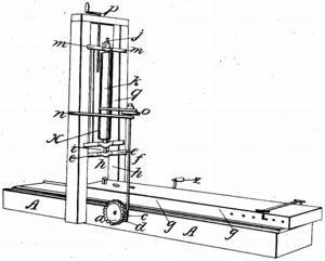
Explanation of the Drawing: A. A. the plank or foundation of the machine. a. cogwheel. d. pedestal or rest for the foot of the upright shaft. S. S. upright shaft. e. Endless screw upon the upright shaft. S. g. g. carriage. a. a. slots in the arm.
Page 4.
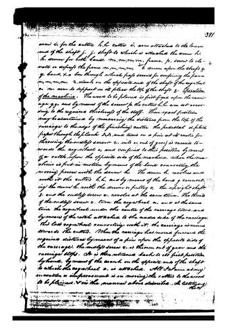
arms i, for the cutters. l, l, cutters i, arm attached to the lower end of the shaft j. j, shaft to which is attached the arm h. h, arm for both bands. m, m, m, m, frame. p, screw to elevate or depress the frame. m, m, m, m, + a arm upon the shaft g. g, band, + a bar through which pass screws for confining the frame m, m, m, m. 2, crank on the opposite end of the shaft of the cogwheel a. m, arm to support in its place the top of the shaft g. Operation of the machine. The wood to be planed is first fixed upon the carriage g, g, and by means of the screw p, the cutters l, l, are set according to the required thickness of the stuff. Their exact position may be ascertained by measuring the distance from the top of the carriage to the edge of the finishing cutter the pedestal d, which passes through the plank D, D, and turns on a pin at its centre for throwing the endless screw c, into or out of gear, is carried towards the cogwheel a, and confined to this position by means of a catch upon the opposite side of the machine. When the machine is put in motion by means of the band connecting the moving power with the arm h. The arm h, revolves and with it the cutters l, l, and by means of the band g connecting the arm h, with the drum or pulley o, the upright shaft g, and the endless screw c, revolve at the same time. The threads of the endless screw c, turn the cogwheel a, and at the same time, the cogwheel under the centre of the carriage turns, and by means of the ratch attached to the under side of the carriage, the last cogwheel connecting with it, the carriage is moved towards the cutters. When the carriage has moved forward the required distance by means of a pin upon the opposite side of the carriage, the endless screw c, is thrown out of gear and the carriage stops. It is then returned back to its first position by hand, by means of the crank on the opposite end of the shaft to which the cogwheel a, is attached. All I have as my invention or improvement is in moving the cutters to the wood to be planed, & in the manner above described. I testify my
Page 5.
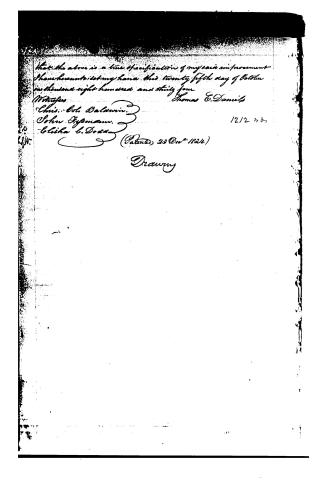
That the above is a true specification of my said improvement, I have hereunto set my hand this twenty-fifth day of October in the year one thousand eight hundred and thirty-four.
Thomas E. Daniels
Witnesses:
Chris. Col. Balawin
John Tyson
Elisha L. Dodd
(Patented 23 Dec 1834)
Drawing
12/2 20
Published accounts: journal notice
Notice in the monthly list of patents
Journal of the Franklin Institute, new ser., vol. 15 (1835), p. 144 · View the page
621. Planing machine. -Thomas E. Daniels, Worcester, Mass.
Published accounts: journal notice
Notice in the monthly list of patents, with remarks
Journal of the Franklin Institute, new ser., vol. 16 (1835), p. 33 · View the page
51. For a Planing Machine; Thomas E. Daniels, Worcester, Worcester county, Massachusetts, December 23.
Remarks. A vertical shaft is to revolve in a suitable frame, with collars to keep it in its proper position. The frame in which the shaft revolves, slides in vertical cheeks, to admit of its being raised or lowered. Two arms project out at right angles from the shaft, and these have slots in them to receive the cutters by which the board is to be planed. VOL. XVI.-No. 1.-JULY, 1835. 5 This is to be secured upon a horizontal carriage, moved forward by a pinion acting upon a rack on its lower side. The general operation of the machine has nothing in it of novelty, and "the moving the cutters to the wood to be planed," constitutes the whole of the claim; that is, the raising or lowering of the slide in which the cutters work, instead of raising and lowering the bed, to adapt the machine to stuff of different thickness. We could refer to several machines in which the cutters are moved to adapt them to the thickness of the wood; of these, one is mentioned in vol. ix., p. 313, in which "the shaft has a sliding motion in the collars, to adapt it to stuff of different thicknesses," and there is a claim to "The sliding motion of the wheel, by which various thicknesses may be planed."
DATAMP: illustration
Illustrations from DATAMP

DATAMP (Directory of American Tool and Machinery Patents), via the Internet Archive · Archived DATAMP page
About this record
- Patentee
- DATAMP, Burke's List of Patents (1847)
- Date
- the Name and Date index of patents, DATAMP, USPTO records
- Invention
- DATAMP
- Listed in
- the Name and Date index of patents, DATAMP, USPTO records, Jim Shaw's X-patent list, the Journal of the Franklin Institute, Burke's List of Patents (1847)
- The name conflict was settled by Burke's 1847 list.
- Burke's 1847 Patent Office list gives the same patent.