

Drawings and documents
National Archives restored drawings: drawing
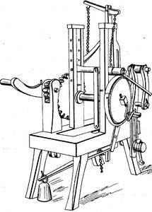
Jona Mulford's Patent Drawing for a Machine for Bending Mast and Truss Hoops

National Archives, Restored Patent Drawings (Record Group 241) · Full-size scan at the National Archives · Catalog record
Show the text on the drawing Hide (51 words)
Words on the drawing as machine-read by the National Archives; not checked. Useful mainly for searching.
144. WOOD WORKING. / 3. SPECIAL WORK MACHINERY. / [176] Bending Wood. / #100 / ICATION / 8600- X / DIVISION / JONA MULFORD / Bending Mast & Trufs hoops. / Latented 16 Jany 1835. / Drawnby HBridperts Phil / May's 1837 / Jonathan Mulforet's Machine far Bending Ma Trues He / 10Jan'1835
USPTO scan
The patent as scanned by the USPTO
-
 Page 1
-
 Page 2


U.S. Patent and Trademark Office · Google Patents
Show the transcription Hide (438 words)
Machine transcription (LightOnOCR) of the pages as scanned by the USPTO, most of them the handwritten copies made when the records were restored after the 1836 fire. Not checked; it can misread handwriting, so compare it with the scan.
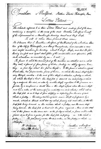
Page 1.
8600X
J. Mulford,
Bending Wood,
Patented Jan. 16, 1835.

A.M. PHOTO-LITH CO. N.Y. (OSBORNE'S PROCESS)
Page 2.
Jan. 16, 1835
Jonathan Mulford, North Liberties, Philadelphia, Penn.
Letters Patent.
The schedule referred to in these Letters Patent and making part of the same, containing a description in the words of the said Jonathan Mulford himself of his improvement in a Machine for bending Mast and Tarp hoops.
To all to whom these presents shall come,
Be it known that J. Jonathan Mulford, of the District of the Northern Liberties of the City of Philadelphia, and State of Pennsylvania, have invented a new and useful machine, for bending Mast & Tarp Hoops, and that the following is a full and exact description of the construction and operation of the said Machine as invented by me — to wit:
The frame to which the several parts of the machine are attached and on which they rest, is formed of four pieces of timber making an oblong square, & resting on four legs about two feet in height: to this frame is attached, opposite to each other, two perpendicular pieces of timber, on which the main shaft in passing through, revolves — to the end of this shaft, is attached a pulley or chuck, on which the hoop is bent — the hoop pole is secured on said pulley or chuck by a wedge in the rim, as also by another shaft, regulated to the pressure required, by a compound or double lever — this shaft is fixed above the main shaft and has a roller at the extremity (immediately over said chuck) which acts on the hoop pole so as to keep it from slipping or departing from the rim of said chuck or pulley — the rotary motion of said main shaft is performed by a crank, attached thereto with two cog wheels passing into each other, so that the hoop pole being secured on the circular chuck or pulley, and the main shaft being turned, the hoop pole is bent into the form required — there is also attached to the frame on the same side as the pulley or chuck, a frame with a roller fixed so as to form a guide for the hoop pole in passing on to the chuck or pulley — The pole passing under the said roller, on the pulley or chuck.
Witnesses,
W. Millhoun
Lewis D. Belair
Jonathan Mulford
392 1835
Published accounts: journal notice
Notice in the monthly list of patents, with remarks
Journal of the Franklin Institute, new ser., vol. 16 (1835), p. 97 · View the page
41. For a Machine for Bending Mast and Truss Hoops; VOL. XVI. No. 2. - AUGUST, 1835. 13 Jonathan Mulford, Northern Liberties, Philadelphia, Pennsylvania, January 16.
Remarks. A cylindrical pulley, or chuck, of iron, is fixed on to the end of a horizontal shaft, with which it is made to revolve, the shaft being turned by means of a wheel and pinion, operated on by a winch. A small roller, formed upon the end of a second shaft, parallel with, and directly above, the former, bears upon the pulley, or chuck, around which the hoop is to be bent, and is borne down upon it by means of weighted levers. The iron passed between these is secured to the chuck by passing under a staple, where it is fastened by a wedge. Upon turning the machine, the iron will be drawn in, and bent into a circular form. There is not any claim made, and the machines for bending hoops, tire, and other articles, are so numerous, that the patentee certainly ought to have designated the character by which this machine is to be distinguished from others.
DATAMP: illustration
Illustrations from DATAMP

DATAMP (Directory of American Tool and Machinery Patents), via the Internet Archive · Archived DATAMP page
About this record
- Patentee
- DATAMP
- Date
- the Name and Date index of patents, DATAMP, USPTO records
- Invention
- DATAMP
- Listed in
- the Name and Date index of patents, DATAMP, USPTO records, Jim Shaw's X-patent list, the Journal of the Franklin Institute, Burke's List of Patents (1847)
- Burke's 1847 Patent Office list gives the same patent.