

Drawings and documents
National Archives restored drawings: drawing
A. Stedman's Patent Drawing for a Method of Making Bedsteads

National Archives, Restored Patent Drawings (Record Group 241) · Full-size scan at the National Archives · Catalog record
Show the text on the drawing Hide (87 words)
Words on the drawing as machine-read by the National Archives; not checked. Useful mainly for searching.
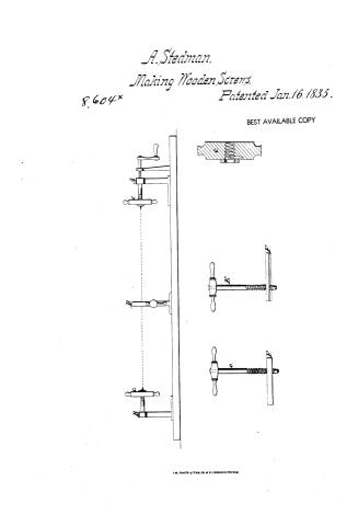
142. WOOD TURNING. / Regular Forms. / Longitudinal Movement. / 750 / A o STEDMAN / Patented 16th Jan 1835 / Making Bedsteads / Asst. ICATION / 8604-X / DIVISION. / A.B. Head-blook Hecl Block / C. Screw Tool / D.Vice D. Vice / E. e. Right &Iesthand a Aupers / F' Box or Plate with Ledges / E' / G. Strickland Del / Patent office faw 17th 1839 / Made under the direction of the lom of Patents the Conformity / with act y.3allarch 1837- / Commiss over of patents
USPTO scan
The patent as scanned by the USPTO
-
 Page 1
-
 Page 2
-
 Page 3


U.S. Patent and Trademark Office · Google Patents
Show the transcription Hide (771 words)
Machine transcription (LightOnOCR) of the pages as scanned by the USPTO, most of them the handwritten copies made when the records were restored after the 1836 fire. Not checked; it can misread handwriting, so compare it with the scan.
Page 1.
A. Stedman,
Making Wooden Screws.
8,604*
Patented Jan. 16, 1835.
BEST AVAILABLE COPY

A.M. PHOTO-LITH. CO., N.Y. (OSBORNE'S PROCESS)
Page 2.
6604X Jan 16, 1835 145
Aaron Steeman
Letters Patent
The Schedule referred to in these Letters Patent and making part of this same containing a description in the words of the said Aaron Steeman himself of his improvement on a machine for making Beadstems.
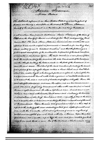
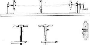
To all to whom these presents shall come, Aaron Steeman of the town of Pottford in the County of Monroe and State of New York sends greeting. Be it known that I the said Aaron Steeman have invented, constructed and applied to use new & useful improvements in machine for making beadstems called by me “a beadstem machine” and that the following is a full & exact description of the construction & operation of the said machine as invented or improved by me. The said machine is composed of two parts the one for cutting the screws on the side & end rails of the beadstem and the other for cutting the holes or cuts in the posts of the beadstems to receive the said screws. That part of the said machine for cutting the screws is composed of two upright stands called a head block and heel block about ten inches high, which may be fastened to a plank or piece of timber or a common work bench with holes or grooves at suitable distances so as to admit the side or end rails of beadstems of different lengths. From the said upright standards and near the upper end are two screws, one on each standard projecting towards each other with a centre pin in each the one a right hand and the other a left hand screw. To each screw is attached a screw tool with handles, each screw tool including the handles is about eleven inches long. Each screw tool is equally fitted to the screws and so constructed as to commence cutting the screws at each end of the rail at the same point. Upon the inner side of each screw tool is a thin cap to regulate the cutting of the screws describing about five depths of a circle and even with the V or cutter which cap may be made of wood or any kind of metal and one eighth of an inch thick or thicker or thinner. Upon the outside of each screw tool is another cap to keep the screw tool from warbling or which may be one inch thick or more. One of the standards or blocks is made movable.
Page 3.
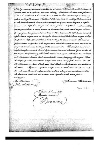
able by means of a screw or otherwise in order to let in the rails between the centre pins and to fasten the ends thereof. Between the two upright standards or head block & heel block is a vice to hold the rails from turning when cutting the screws. That part of the machine for cutting the boxes or nuts in the posts to receive the screws is composed of two screw augers, a right hand and a left hand auger which may be made of steel or cast iron. When made of cast iron a steel cutter is dovetailed into each auger. A accompanying each auger is a box or plate with a ledge on the left hand side of the right hand auger and on the right hand side of the left hand auger, to keep the post in its proper position while cutting the boxes or nuts. The boxes or plates serve as guides to the augers and must be so made as to cause each auger to commence cutting at the same point. The specific new and useful improvements herein before described and claimed by me as the inventor are the following: First the cast iron augers with the cutters dovetailed into the same. Second the boxes or plates accompanying the augers. Third the caps upon the screw tools to regulate the cutting of the screws. Fourth the standards or head block and heel block with the screws attached to the same. By means of these improvements the screws in the ends of the rails and the nuts or boxes in the posts are always cut uniform, so that the head and heel in all cases come together with close joints.
Witnesses
Jas Bellows
John Sutherland
Aaron Headman
7/14 n. 6
(Patented 16 January 1835)
(Drawing made.)
(Drawing.)
DATAMP: illustration
Illustrations from DATAMP

DATAMP (Directory of American Tool and Machinery Patents), via the Internet Archive · Archived DATAMP page
About this record
- Patentee
- DATAMP
- Date
- the Name and Date index of patents, DATAMP, USPTO records
- Invention
- DATAMP
- Listed in
- the Name and Date index of patents, DATAMP, USPTO records, Jim Shaw's X-patent list, Burke's List of Patents (1847)
- Burke's 1847 Patent Office list gives the same patent.