

Drawings and documents
USPTO scan
The patent as scanned by the USPTO
-
 Page 1
-
 Page 2
-
 Page 3
-
 Page 4
-
 Page 5
-
 Page 6
-
 Page 7


U.S. Patent and Trademark Office · Google Patents
Show the transcription Hide (2,303 words)
Machine transcription (LightOnOCR) of the pages as scanned by the USPTO, most of them the handwritten copies made when the records were restored after the 1836 fire. Not checked; it can misread handwriting, so compare it with the scan.
Page 1.
PRINTED SPECIFICATION AVAILABLE
P. Sweet,
Brick Machine.
Patented Feb. 20, 1835
8652x
BEST AVAILABLE COPY

Page 2.
Pelig Sweet Ashatabula Ohio
Letters Patent.
The Schedule referred to in these Letters Patent, and making part of the same, containing a description in the words of the said Pelig Sweet himself of his improvement in Brick making, called "Sweet's Brick Sticks."
To all to whom these presents shall come: Be it known that I Pelig Sweet of Ashatabula in the county of Ashatabula and state of Ohio, have invented a new and useful improvement in the art of making Brick, and that the following is a full and exact description of the construction and operation of the said Machine as invented or improved by me, reference being had to the plates numbered and parts lettered sketched and accompanying this specification.
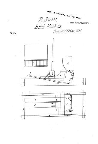
Plate 1. Birdseye view of the frame and several important parts fully described and referred to.
A.A. Side pieces 7½ feet long 3 inches thick 12 inches wide.
B.B. End pieces 3½ feet long 3 do thick 12 inches wide.
Width of the frame from inside to inside 3 feet 1½ inches clear.
Length of the frame from inside to inside 6 feet 8 inches clear.
C.C. 11½ inches from the inside of one end of said frame commences a Mortice into each side piece 5 inches deep, one inch wide to admit the end of the hopper. Mortices to be 8 inches long on the end of each side piece.
D. Roof pile. Immediately in rear of these Mortices is a roof pile framed into side pieces ½ of an inch above their level, said piece 5 inches wide and ¾ inch thick.
E. Stanchion Beams, a piece of timber 7 inches wide and 4 inches thick, framed into and on a level with the roof pile, and into, and 4 inch above the level of the rear end piece.
F. Mortices for the Stanchions 7½ inches from each side 6 inches long 1 inch wide 3 inches diameter from each other and through thickness.
G. The foot lever to give motion to the knife, is formed of a piece of plank
15
Page 3.
1½ inches thick 5 feet long firmly ironed by rivets to a flat roller turning on 2 inch gudgeons, which said rollers play immediately under the rear of the crop sill and 3 inches below said sill. The plank in rear of the crop sill and roller is reduced to 6 inches wide on the left of the stanchions, but on the roller and at the front end is 19 inches wide see 8, 8.
H. Irons passing through the knife. To the upper side of the front or wide end of said lever, are attached two iron shaped like a mason’s trowel. The blade part spiked to the plank by 3 spikes (2 in front and one in rear) and the handle part curved gently over from the blade 5 inch diameter and passing through the knife 16 in apart and at equal distance from the sides.
I see plate second. The knife for shaving the brick to a level with the surface of the moulds is formed of iron ½ of an inch thick, either of strong sheet or malleable wrought iron 13 inches wide and 24 inches long gently curved over to the front of the top like a curious knife — strengthened at the bottom by a bar of iron ½ inch thick 1½ inches wide and 28½ inches long riveted on and receives the two iron spurs of the foot lever through it together with the main iron of said knife B. Brown (see plate 24) are sawed in to each side piece to admit each end of the knife and steady it; the grooves varying two inches in 9 from perpendicular, the upper part of the knife having the greatest front projection. These grooves are continued as high as the top of the generators by means of 2 pieces of cast iron extending from the top of the frame to the upright part of the hopper 2 inches wide ¾ inch thick, grooved from the inner edges and attached by screws to the front of the hopper.
Plate 3. a side view of the machine with the manner in which the foot lever is hung and attached to the knife.
K. The ends of the hopper, are composed of 1½ inch plank inserted into side pieces by 8 inch tenons (see letter C) and pieces 2½ feet high 4 inches wide. During the first 9½ inches from the shoulder of the tenon or surface of the side piece each end piece slopes or projects to the front at a slope of 3 inches for every 9. From this point they ascend perpendicularly to the top. One half inch is grooved from the inner part of each end piece to the height
Page 4.
height of 9 1/4 inches, this being the height of the propeller which acts immediately under the groove shoulders. The front and rear sides of the hopper are formed of boards one inch thick, upraised from one another where the hopper ascends perpendicularly. The end pieces of the hopper from inside to inside will be 30 1/2 inches distant. This space is partly occupied in front by the generators (see letters h, h, h, h, on plate first) which are seven pieces of wood edged in the rear and 1/8 inch thick in front. Two of these may be formed semi-generators, being attached to the inner front of each end piece of the hopper. The remaining 5 stand at 1/2 inches distance across the open front of the hopper. Between these the mortars is pressed forward into the molds as the lever descends. They assist in forming the brick, and protect the molds from injury. These 5 pieces are morticed into a bottom board that extends from the knife groove to the top side in rear of the hopper, and are halved into the perpendicular bottom front of the hopper, and secured there by a strip of iron 1/8 inch thick and one inch wide which is attached to the hopper by screws passing through it into the front board of the hopper.
The molds (see plate 3rd letter M) may be of any size or shape to suit the maker and such parts of the machine as are necessary vary accordingly. They are described as forming bricks of common size. The bars of the mold are all crosswise 1/8 of an inch thick. Each bar of the mold is covered and protected by a generator as the mold is placed edgewise in front of them to receive the mortars, the molds resting in two sloping grooves cut into the upper part of the side pieces of the frame.
The mold stay is of two parts. First a 1 1/2 inch board (see letter L) falling a little below the molds in front of them where it turns on 1 1/2 inch gudgeons let into the side pieces chamfered to 3/4 inch thick up at the other edge. The molds may be raised to a position to receive the mortars by raising up the board, around which together with the moulds the armarm stay is thrown to hold the molds firmly to their place until filled. This board prevents the bottom of the molds from being pressed out and serves for the molds to rest on (ready for the carrier) when it falls down on two sloping blocks, the
Page 5.
The molds being full and the back or arm stay thrown up and withdrawn by a downward pressure on the front part of it by the man at the lever. All the arm stays, an arm is attached to each end of the hopper by an iron bolt one inch diameter the head inward, which bolts pass through the end pieces of the hopper and are secured by nuts, said bolts are 10 inches from the surface of the side frame piece and 8 inches in rear of the front. These arms are united by a substantial cross piece 5 inches wide firmly affixed to the ends of the arms, but the rear ends of the arms play on the bolts as the arm stay is raised or brought down to confine or liberate the molds either or both their arms may extend to the rear of the hopper at a convenient slope, and may be united there by a cross piece for the convenience of having the man at the lever handle the molds with more facility.
IV. An end view of the molds placed to receive the mortar and supported by the board or back, and arm stays.
O. The Stanchions are 12 inches high 3 inches thick & 6 inches wide passing through the stanchion bearer by inch tenons and keyed below, they being placed two inches apart and 5 inches in rear of the crosspiece, and firmly secured in their rear by two braces two inches from each other.
P. The Propelling Lever is a firm piece of timber four feet 9 inches long and 3 inches thick enlarging towards the main end where it terminates in a semicircular shape. Through the center of this circular termination is a hole bored with iron to 1/2 inch diameter through which passes the bolt, and through the stanchions on which the lever plays. From the center to the circumferential line of the wooden part of the semicircle the distance is 3 1/2 inches. Around the circumferential surface of the semicircular end of the Lever is affixed firmly the segment of a cast iron cogwheel to the amount of a half circle exactly of 5 1/2 inch base and 5 1/2 inch cogs, 1 1/2 inches wide 1/2 inch space between cogs. The number of cogs will be ten, and apparently at each end of the iron a cog gives place to a 1/2 inch hole through the base of the iron. Along the upper part of the lever is a wrought iron back stay about 1 inch
Page 6.
inches long rounded to a bolt at its front extremity, passing through the hole in the end of the cog segment, and is screwed by a nut. A bolt passes through the near or lower end of the cog segment through the written part of the lever in the rear of the centre of the same circle, and through the back stay where it is notched. The back stay at its extreme rear is further secured to the lever by a rivet. The bolt on which the lever plays is secured by a nut.
Q Q. The advanced propeller is of two parts, viz, the beam, and the head. The beam is three feet long 2 inches thick, 10 inches of its front end are 6 3/4 inches wide, and its rear part 2 1/2 inches of firm timbers morticed into the centre of the head plank by a double tenon and braced to the same on each side. The upper portion of the head is the same as the fore head plank, 2 inches thick 8 1/4 inches wide and 30 1/2 inches long, pinned to each other at the top, the upper plank resting at its centre on the forward or wide portion of the beam, and the front of the advanced propeller projects forward on the same slope as the under part of the hopper the space whereof it exactly fills. Thirteen inches in the immediate rear of the front board is the first of eleven edges of the same base distance and height, as in the cog segment, the base being a straight piece of iron 1 1/2 inches wide inserted into the centre of the beam the cog extending from and above the surface and mechanically acting with the edge of the segment in giving motion to the advanced propeller. This latter cog iron is bolted at each end to the beam immediately under the bolt on which the lever hangs is a cast iron roller 3 inches diameter and 2 inches long turning on inch guigeons in the stanchion bearer, and just above the surface of the bearer for the beam to play on. These guigeons should rest in steel boxes being subject to much pressure.
Plate 3. is a view of the open molds set in position to receive the mortar; also a front view of the hopper.
The operation of the machine is; The lever is thrown up perpendicularly which draws the head of the advanced propeller to the rear of the hopper which will contain enough for 100 brick. From the shape of the hopper there is little friction to
Page 7.
To hinder the descent of the mortar, the space between the head of the advanced propeller and generators and molds is filled; the lever is brought down which throws the head of the advanced propeller forward against the mass of mortar between it and the molds, the mortar cannot escape but is forced through the generator into the mold (which maybe twice filled by bringing the lever once down) the molds are at once filled perfectly; the man at the lever places one foot on the foot lever, the knife is forced upward (touching the surface of the molds) between the generator and molds, the mortar in the molds is thus separated from the mass in the hopper, the hand of the man touches the arm stay with a downward motion and the molds fall forward filled ready for the carrier, the knife is drawn back by pulling the foot lever upward and the same process repeated.
The subscriber claims exclusively the discovery of properly confining and supplying the mortar properly placing the molds, and forcing the mortar into the molds by the immediate action of the propeller so as to leave no brick imperfect. The operation of the machine is rapid; sure to produce perfect bricks (moulded in sand) and is the best labour saving machine for the purpose within his knowledge.
Witnesses
P. A. Spencer
Wm. Woodbury
Charles Wood
(Drawing)
Pelay Sweet
(25 L.S.)
Published accounts: journal notice
Notice in the monthly list of patents, with remarks
Journal of the Franklin Institute, new ser., vol. 16 (1835), p. 164 · View the page
21. For a Brick Striker; Peleg Sweet, Ashtabula, county of Ashtabula, Ohio, February 20.
Remarks. The drawing, which is referred to through the whole description of this machine, is so imperfect, as to afford a very inadequate idea of its construction and mode of operation, and we shall not attempt to decypher it. The claim is, "exclusively the discovery of properly confining and supplying the mortar, properly placing the moulds, and forcing the mortar into the moulds by the immediate action of the propeller, so as to leave no brick imperfect. The operation of the machine is rapid, sure to produce perfect bricks, and is the best labour saving machine for the purpose within his knowledge." This claim is altogether defective, as it refers to the thing done, instead of to the means, or machinery, by which it is effected.
About this record
- Patentee
- DATAMP
- Date
- the Name and Date index of patents, DATAMP, USPTO records
- Invention
- DATAMP
- Listed in
- the Name and Date index of patents, DATAMP, USPTO records, Jim Shaw's X-patent list, the Journal of the Franklin Institute