

Drawings and documents
USPTO scan
The patent as scanned by the USPTO
-
 Page 1
-
 Page 2
-
 Page 3
-
 Page 4
-
 Page 5
-
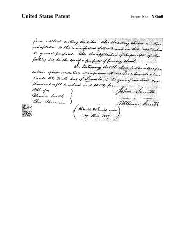 Page 6


U.S. Patent and Trademark Office · Google Patents
Show the transcription Hide (1,612 words)
Machine transcription (LightOnOCR) of the pages as scanned by the USPTO, most of them the handwritten copies made when the records were restored after the 1836 fire. Not checked; it can misread handwriting, so compare it with the scan.
Page 2.
United States Patent
Patent No.: X8660
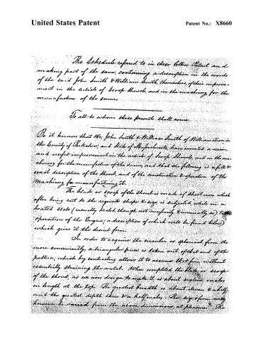
The Schedule referred to in these letters Patent and making part of the same, containing a description in the words of the said John Smith & William Smith, themselves, of their improvement in the article of scoop shovels, and in the machinery for the manufacture of the same.
To all to whom these presents shall come.
Be it known that We, John Smith & William Smith of Williamstown in the County of Berkshire, and State of Massachusetts, have invented a new and useful improvement in the article of scoop shovels, and in the machinery for the manufacture of the same, and that the following is a full & exact description of the shovel, and of the construction & operation of the machinery for manufacturing it.
The blade or scoop of the shovel is made of sheet iron which after being cut to the requisite shape & size, is subjected, while in a heated state (usually heated, though not necessarily & invariably so) to the operation of the Engine (a description of which will be found below) which gives it the desired form.
In order to acquire the circular or spherical form the more conveniently, a triangular piece is taken out of that end of the pattern, which by contracting allows it to assume that form, without essentially straining the metal. When completed the blade or scoop of the shovel, as we now design to make it, is about sixteen inches in length at the top. The greatest breadth is about eleven & a half, and the greatest depth three & a half inches. The size & form may however be varied from the above dimensions, at pleasure. The
Page 3.
United States Patent
Patent No.: X8660
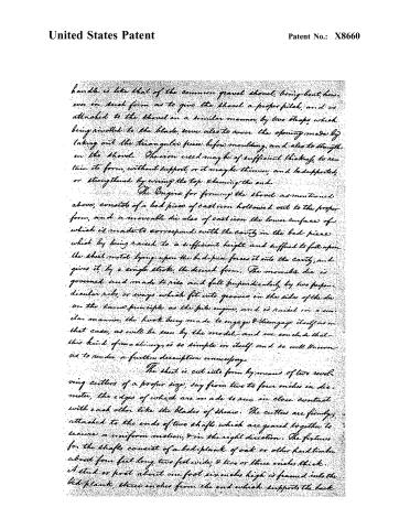
handle is like that of the common gravel shovel, being bent, however in such form as to give the shovel a proper pitch, and is attached to the shovel in a similar manner, by two straps, which being rivetted to the blade, serve also to cover the opening made by taking out the triangular piece before moulding, and also to strengthen the shovel. The iron used may be of sufficient thickness, to retain its form, without support, or it may be thinner, and be supported, or strengthened by wiring the top, & hemming the end.
The Engine for forming the shovel, as mentioned above, consists of a bed piece of cast iron hollowed out to the proper form, and a movable die also of cast iron the lower surface of which is made to correspond with the cavity in the bed piece which by being raised to a sufficient height and suffered to fall upon the sheet metal lying upon the bed-piece forces it into the cavity, and gives it, by a single stroke, the desired form. The movable die is governed and made to rise and fall perpendicularly, by two perpendicular ribs, or ways which fit into grooves in the sides of the die on the same principle as the pile engine, and is raised in a similar manner, the hook being made to engage & disengage itself as in that case, as will be seen by the model, and we conclude that this kind of machinery is so simple in itself and so well known as to render a further description unnecessary.
The sheet is cut into form by means of two revolving cutters of a proper size, say from two to four inches in diameter, the edges of which are made to run in close contact with each other like the blades of shears. The cutters are firmly attached to the ends of two shafts which are geared together to secure a uniform motion, & in the right direction. The fixtures for the shafts consist of a bed-plank of oak or other hard timber about four feet long, two feet wide, & two or three inches thick. A stud or post about one foot six inches high is framed into the bed-plank, three inches from the end which supports the back
Page 4.
United States Patent
Patent No.: X8660
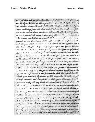
end of both the shafts. The other end of the lower shaft is supported by a pillow, or bearing, placed upon the bed plank near the cutter, while the end of the upper shaft is supported by an arm extending from the stud or post above the shaft nearly to the cutter, which leaves the space between the shafts entirely clear, so as to permit the sheet to pass freely between them (see model). The cutters are kept in close contact by means of a stand placed at the back end of the upper shaft which prevents it vibrating in that direction, and a screw at the opposite end of the lower shaft. A spiral spring occupies the space between the stud or post, and the gearing upon the upper shaft, which prevents it from vibrating in the opposite direction, and another spring is thrown around the lower shaft upon the other side of the stud, to hold it against the point of the screw at the end, and thus both shafts are prevented from vibrating in either direction (see model). This distance which the edges of the cutters are made to pass each other, is regulated by means of a screw directly over the journal of the upper shaft, and two spiral springs around the pins which hold the cap below the shaft (see model). By means of this apparatus the cutters may be entirely separated, and brought in contact again at pleasure, so as to commence cutting at any point in the middle of the sheet of leather. For cutting in a right line the sheet is placed upon a carriage which extends from the cutters to the end of the bed plank, and is elevated so as to bring the sheet exactly on a level with the point of contact of the cutters. The carriage is made to pass the cutters in a right line, by means of two lips, one upon each side of it, which fit closely to the sides of the projection, or elevation of the bed plank upon which it lies (see model). But for cutting the shovel patterns into form, this carriage is removed, and another placed in its stead, which has two pins projecting from its lower surface, one of which is placed near the forward end, on a line with the centre of the pattern, and the other
Page 5.
United States Patent
Patent No.: X8660
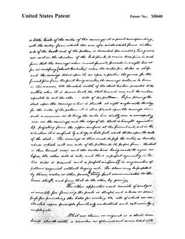
a little back of the centre of the carriage, at a point corresponding, with the centre, from which the arc of a circle which forms either side of the back end of the pattern, is described (see model). Two grooves are cut in the elevation of the bed-plank, to receive these pins in such form that the carriage when moved forward, proceeds in a right line as far as necessary (about two inches) when the centre pin strikes a stop and the carriage turns upon it, as upon a pivot — the groove for the forward pin from the point being circular, the carriage continues to turn in this manner, till the whole width of the sheet has been presented to the cutter, when it is drawn back, the sheet turned over, and the motion repeated to cut the other side of the pattern. Before placing the sheet upon the carriage, a line is struck at right angles with the edge for the centre of the pattern: it is then placed upon the carriage in such a manner as to bring the centre line directly over a corresponding one on the carriage, and the edge of the sheet is brought against a lip projecting from the upper surface at the forward end, and in this situation it is confined by a dog, or hold fast, which strikes upon the centre of the sheet. The carriage is then made to pass the cutter, as described above which cuts one side of the pattern to its proper form: the sheet is then turned over, and the centre lines being made to agree as before, the other side is cut; and thus a perfect symmetry in the two sides is secured and a perfect uniformity in any number of patterns required without laying out. The sheers may be propelled by steam, water, or other power, being first communicated to the lower shaft, and from that to the other, by gearing.
The other apparatus used consists of swedges or moulds for forming the pads or straps, and a lever or screw press for punching the holes for riveting &c, all of which are constructed upon principles familiarly understood and extensively employed.
What we claim as original is a sheet iron scoop shod with a circular or spherical end moulded into
Page 6.
United States Patent
Patent No.: X8660
form without cutting the sides. Also the rotary shears, in their adaptation to the manufacture of shreds and in their application to general purposes. Also the application of the principle of the falling die, to the specific purpose of forming shreds.
In testimony that the above is a true specification of our invention or improvement we have hereunto set our hands this tenth day of December, in the year of our Lord one thousand eight hundred and thirty four.
Witnesses
Dennis Smith
Chas. Shearman
John Smith
William Smith
(Received & Recorded
by Rec. 1834)
Published accounts: journal notice
Notice in the monthly list of patents, with remarks
Journal of the Franklin Institute, new ser., vol. 16 (1835), p. 168 · View the page
31. For Scoop Shovels, and Machinery for manufacturing them; John and William Smith, Williamstown, Berkshire county, Massachusetts, February 25.
Remarks. The claims made "as original, is a sheet iron scoop shovel, with a circular or spherical end, moulded into form without cutting the sides. Also the rotary shears, in their adaptation to general purposes. Also the application of the principle of a falling die to the specific purpose of forming shovels." The particular form given to the shovels is described in the specification, but is not represented in the drawing, and as we have not seen it, we venture to hope that there is more novelty in this, than in the "machinery for manufacturing the same," which consists of the common revolving shears, or cutters, for cutting the metal, and the common drop-press, furnished with dies to give it the intended form.
About this record
- Patentee
- DATAMP
- Date
- the Name and Date index of patents, DATAMP, USPTO records
- Invention
- DATAMP
- Listed in
- the Name and Date index of patents, DATAMP, USPTO records, Jim Shaw's X-patent list, the Journal of the Franklin Institute, Burke's List of Patents (1847)
- Burke's 1847 Patent Office list gives the same patent.