

Drawings and documents
USPTO scan
The patent as scanned by the USPTO
-
 Page 1
-
 Page 2
-
 Page 3
-
 Page 4


U.S. Patent and Trademark Office · Google Patents
Show the transcription Hide (1,234 words)
Machine transcription (LightOnOCR) of the pages as scanned by the USPTO, most of them the handwritten copies made when the records were restored after the 1836 fire. Not checked; it can misread handwriting, so compare it with the scan.
Page 1.
8722X
S. FAIRLAMB & J. L. GILPIN.
INKING TYPE.
Patented Mar. 27, 1835.

Page 2.
Mar 27 1835
Samuel Fairlamb & John L. Gilpin
8722 X Letters Patent
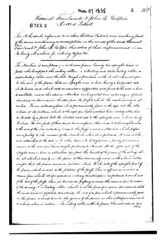
The Schedule referred to in these Letters Patent and making part of the same containing a description in the words of the said Samuel Fairlamb & John L. Gilpin themselves of their improvement in an inkling Machine for inking types &c.
The Machine is composed of a cast iron frame having two upright sides or posts, which support the inking roller, a vibrating and distributing roller, a distributing roller and the ink trough or fountain with its roller and scraper. In the rear of the frame there is an upright arm or lever having a horizontal axis at its lower end which rests on carriages or supports and permits the arm or lever to oscillate; and on this axis are attached two horizontal levers extending in opposite directions, one towards and the other from the front to which the machine may be attached. The one extending from it is permanently fixed on the axis but the other is loose at its fulcrum which is the axis and has a crooked lever loosely attached to its side by a pivot bolt the shortest end next to the upright arm or lever being hooked. The two front of these levers have cups on their ends to hold weights, and to the end of the one extending toward the front a cord is attached which passes over a pulley to the runner of the Machine when it is fastened. A cord is likewise attached to the end of the other lever which passes over a pulley fixed on a carrier in the rear (and) has a weight fastened to its end. At the upper end of the upright arm or lever is attached, by a joint the handle of the frame of the inking roller, all which is nearly in the form of those commonly used with a hand roller except that the frame moves on friction wheels. On the side of the upright front of the frame, which is next to the platen of the press, there is affixed on carriages a runner from which straps extend in contrary directions (and) are fastened to each end of the bed of the press, there are two cords passing around the runner (and) to one (end) of the driving & vibrating roller, which is in the form of a screw, (and) around which the cords wind in opposite directions; the end of a pin which is permanently fixed in the frame is made to enter the groove of the screw on this roller (and) causes it to vibrate when in motion. The inking roller with its frame & handle rests on two (shoes)
Page 3.
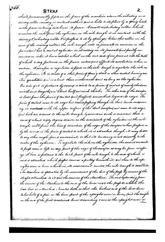
wheels permanently fixed on the frame of the machine above the vibrating and driving roller coming in contact with it and is held to its place by a spring latch on the frame entering notches in its frame. A small distributing roller which receives the ink from the cylinder in the ink trough is in contact with the driving & vibrating roller & is pressed to it by springs; below this roller in the rear of the driving roller, the ink trough rests on journals in carriers in the frame (and has a metal cylinder in it resting on its journals (and partly immersed in ink); it has a ratchet wheel on the out end of one journal into the teeth of which a dog fastened on the frame enters and effects its revolution when in motion. A scraper or regulator is fixed on the ink trough to regulate the ink on the cylinder. It is made of a thin piece of spring steel or other metal having similar qualities (and is about three inches wide (and as long as the cylinder. One side of it is fastened by screws or rivets to a piece of metal of nearly the same width and length (and about half an inch thick. The other side of the scraper is loose from the piece of metal (and projects somewhat beyond its edge. The piece of metal near to its edge has screws passing through it, their lower ends coming in contact with the upper surface of the steel scraper (and near to its edge, (and both are secured to the ink trough by screws in such a manner that a cord of about sixty degrees drawn on the semicircle of the cylinder in the ink trough will form the line of direction of the edge of the scraper when pressed on by the screws in the piece of metal to which it is attached though it may be set to any other angle found convenient; so that its tendency is not directly to the centre of the cylinder. To regulate the ink on the cylinder the screws are made to press more or less on any part of the edge of the scraper as may be found necessary. A lever is fastened to the back part of the ink trough to the end of which a cord is attached which passes round a pulley beneath it, and then to the upright arm or lever which in its movement causes the ink trough to oscillate. The machine is operated by the movement of the belt of the press by means of the straps attached to it and the source of the machine. The end extending from the source of the machine to the end of the lever near the press to which the loose lever is attached is so that the hooked end of the loose lever takes hold of a pin in the lower part of the upright arm or lever, (and the weight on the end of the first mentioned lever descending carries the upright arm or lever
Page 4.
8722X
3.
move forward, (and with it the inkling roller &c. When this weight and lever have descended far enough the end of the crooked (and loose) lever meets a permanent fixture which detaches it from the upright arm or lever when the weight on the permanent lever in the opposite direction carries it (and with it the inkling roller &c) to their first position, where they are held by the spring latch on the frame entering notches in the frame of the ink roller (and from which it is relieved by the limpan when being raised striking & holding back said latch. The ink is distributed on all the rollers by the driving and vibrating roller which is attached to the source of the machine by cords; it having been first communicated to the small distributing rollers by the movement of the ink troughs &c.
What we claim as of our invention is the application or manner of applying an elastic scraper to effect the regulation of printing ink on a cylinder or roller, and the manner of applying granitating substances or heavy bodies to propel an inkling roller over a form of type &c.
Witnesses
Alexander H. Harper
J. W. Harper
Samuel Fairlamb
John L. Gilpin
(Drawing)
Published accounts: journal notice
Notice in the monthly list of patents, with remarks
Journal of the Franklin Institute, new ser., vol. 16 (1835), p. 253 · View the page
65. For an Inking Machine, for the hand printing press; Samuel Fairlamb, and John L. Gilpin, city of New York, March 27.
Remarks. This apparatus resembles, very closely, some of those which we have previously noticed, as intended for the same purpose. The claim made is to "the manner of applying an elastic scraper to effect the regulation of the printing ink; and the manner of applying gravitating substances, or heavy bodies, to propel inking rollers over a form of type." Thus limited, we see nothing adverse to the sustaining of the claim; but there does not appear to us to be any improvement in the general construction of the machinery, calculated to remove the objections which, after a fair trial, printers have urged against it. It is more subject to be out of order than a roller boy, and is not so easily replaced; it does not work so equally as a good boy, and when it works badly, it is of no use to beat it. These observations apply, not specially to the particular machine before us, but generally to all of a similar kind which have been brought into use.
About this record
- Patentee
- DATAMP
- Date
- the Name and Date index of patents, DATAMP, USPTO records
- Invention
- DATAMP
- Listed in
- the Name and Date index of patents, DATAMP, USPTO records, Jim Shaw's X-patent list, the Journal of the Franklin Institute, Burke's List of Patents (1847)
- Burke's 1847 Patent Office list gives the same patent.