

Drawings and documents
USPTO scan
The patent as scanned by the USPTO
-
 Page 1
-
 Page 2
-
 Page 3
-
 Page 4
-
 Page 5


U.S. Patent and Trademark Office · Google Patents
Show the transcription Hide (1,128 words)
Machine transcription (LightOnOCR) of the pages as scanned by the USPTO, most of them the handwritten copies made when the records were restored after the 1836 fire. Not checked; it can misread handwriting, so compare it with the scan.
Page 1.
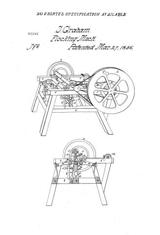
NO PRINTED SPECIFICATION AVAILABLE
8724X
S. Graham.
Flocking Mach.
Patented Mar. 27, 1835.
Page 2.
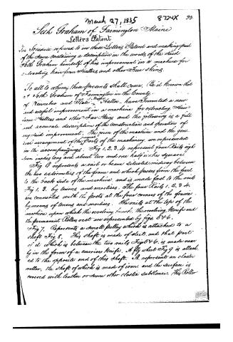
March 27, 1835 8724X 93.
Jeth Graham of Farmington Maine
Letters Patent
The Schedule referred to in these Letters Patent and making part of the same containing a description in the words of the said Jeth Graham himself of his improvement in a machine for extracting hair from Hatters and other Furs Skins.
To all to whom these presents shall come, Be it known that Jeth Graham of Farmington in the County of Kennebec and State of Maine have invented a new and useful improvement in a machine for extracting Hair from Hatters and other Furs Skins and the following is a full and accurate description of the construction and operation of my said improvement. The form of the machine and the general arrangement of the parts of the machinery, are represented in the accompanying figures. Fig 1, 2, 3, 4 represent four Rails eight inches long and about two and one half inches square.
Fig 4 represents a rail or beam situated midway between the two extremities of the frame and which passes from the front to the back side of the machine, and is made fast to the rails Fig 1, 3, by tenons and mortises. The four Rails 1, 2, 3, 4, are connected with the posts at the four corners of the frame by means of tenons and mortises. The rails at the top of the machine upon which the revolving brush, the revolving Knife and the permanent Rollers rest are represented by figs 5 & 6.
Fig 7, Represents a small pulley which is attached to a shaft Fig 8. This shaft is made of steel, and that part of it which is between the two rails Fig 5 & 6, is made nearly in the form of a carriers knife. A fly wheel Fig 9 is attached to the opposite end of this shaft. A, represents an elastic roller, the shaft of which is made of iron, and the surface is covered with leather or some other elastic substance. This Roller
Page 3.
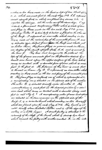
revolves in two boxes made in the head or top of two steel springs a. a. which are made fast to the rails Figs 1 & 3. b. b. represent small upright posts in which are placed two screws c. c. to regulate the springs. All the rollers are of the same size. C represents a permanent compressing Roller which is made of iron and plays in Boxes made in the two rails Figs 5 & 6. A corresponding Roller B is similarly situated is placed on the other side of the Knife. D represents an iron roller which revolves in two boxes made at the extremities of the moveable frame I. and is situated equi-distant from the knife and elastic roller below them. This frame plays in grooves made in the inner surface of the small upright posts d. d. and is moved by the lever E. This lever and consequently the roller at the top of the frame are made fast in the position desired by a small iron hand upon the upper surface of the lever which comes in contact with a serrated piece of iron which is made fast to the post d. The fulcrum of this lever is made fast to the rail or beam Fig 0. G represents an iron roller which revolves in boxes made in the two end pieces of the moveable frame H. This frame plays on two pivots one of which is represented at e. a corresponding one is situated on the opposite side of the machine. The roller G is situated directly under the roller C. This moveable frame is made fast in the desired position by a small iron hand which comes in contact with a serrated spring made fast in rail Fig 2. A corresponding roller frame and spring are situated in the same manner on the opposite side of the knife. I. is a circular brush which revolves in two boxes f. f. which are placed upon the rails Figs 5 & 6. This brush is situated directly above the elastic Roller and is of the size of the rollers or a little larger. A small pulley is attached to the extremity of the shaft of the brush which is driven by a band which connects this pulley with another marked K. in the in the
Page 4.
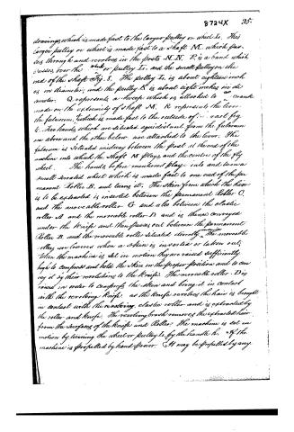
drawings which is made fast to the larger pulley on wheel I. This larger pulley or wheel is made fast to a shaft M, which passes through and revolves in the posts N.N. P is a band which passes over the wheel or pulley I, and the small pulley on the end of the shaft Fig. 8. The pulley I is about eighteen inches in diameter, and the pulley K is about eight inches in diameter. Q represents a sweep which is attached to an crank made on the extremity of shaft M. R represents the lever the fulcrum, which is made fast to the outside of the rail Fig. 6. Two hands which are situated equidistant from the fulcrum one above and the other below, are attached to the lever. The fulcrum is situated midway between the post at the end of the machine into which the shaft M plays, and the centre of the fly wheel. The hands before mentioned play into and turn a small serrated wheel which is made fast to one end of the permanent Roller B, and turning it. The skin from which the hair is to be extracted is inserted between the permanent Roller C, and the moveable roller G and also between the elastic roller A and the moveable roller D, and is then conveyed under the knife and then passes out between the permanent Roller B, and the moveable roller situated directly under the moveable roller, are lowered when a skin is inserted or taken out; when the machine is set in motion they are raised sufficiently high to compress and hold the skin in the proper position and to convey it by their revolving to the knife. The moveable roller D is raised in order to compress the skin and bring it in contact with the revolving knife, as the knife revolves the hair is brought in contact with the revolving elastic roller and is extracted by the roller and knife. The revolving brush removes the extracted hair from the surfaces of the knife and Roller. The machine is set in motion by turning the wheel or pulley I, by the handle H. If the machine is propelled by hand power. (It may be propelled by any
Page 5.
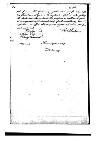
36. …
Published accounts: journal notice
Notice in the monthly list of patents, with remarks
Journal of the Franklin Institute, new ser., vol. 16 (1835), p. 252 · View the page
61. For a Machine for Extracting Hair from Skins; S. G. Ladd, assignee of S. Graham, Farmington, Kennebec county, Maine, March 27.
Remarks. This machine is furnished with several rollers, between which the skin is to pass, in order to its being presented to a revolving knife, by which the hair is to be cut off. The claim is to "the application of the revolving knife, the elastic and other rollers, to this purpose, as well as the general arrangement of the several parts of the machinery, and their application to effect the purpose designed, as specified and described." If memory serves us correctly, the terms of this claim are too broad and general, as we believe that skins have been passed between rollers, and the hair separated from them, by revolving knives, prior to the obtaining of this patent.
About this record
- Patentee
- DATAMP
- Date
- the Name and Date index of patents, DATAMP, USPTO records
- Invention
- DATAMP
- Listed in
- the Name and Date index of patents, DATAMP, USPTO records, Jim Shaw's X-patent list, the Journal of the Franklin Institute, Burke's List of Patents (1847)
- Burke's 1847 Patent Office list gives the same patent.