

Drawings and documents
USPTO scan
The patent as scanned by the USPTO
-
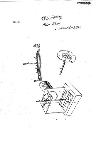 Page 1
-
 Page 2
-
 Page 3
-
 Page 4
-
 Page 5
-
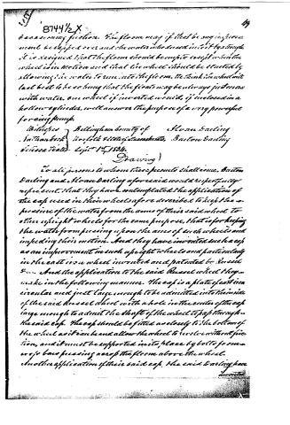 Page 6
-
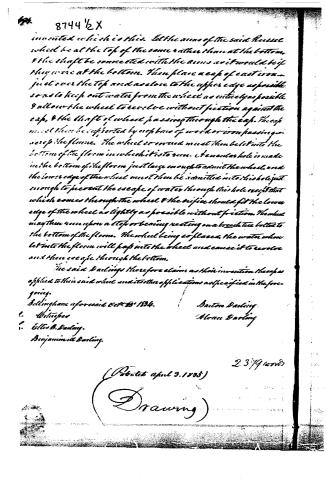 Page 7


U.S. Patent and Trademark Office · Google Patents
Show the transcription Hide (2,228 words)
Machine transcription (LightOnOCR) of the pages as scanned by the USPTO, most of them the handwritten copies made when the records were restored after the 1836 fire. Not checked; it can misread handwriting, so compare it with the scan.
Page 1.
8744½X
By B. Darling,
Water Wheel.
Patented Apr 3, 1835.
Page 2.
April 8, 1835
Hiram Darling and Barton Darling
8744 ½x
Letters Patent.
The schedule referred to in these Letters Patent, and making part of the same, containing a description in the words of the said Hiram Darling and Barton Darling themselves of their improvement in Water Wheels for moving Mill works, Machinery &c.
To all to whom these these presents shall come, be it known that we Hiram Darling and Barton Darling both of Bellingham in the county of Norfolk and state of Massachusetts have invented a new and useful improvement in Water Wheels for moving Mill works, Machinery and other things by water power, and that the following is a full and exact description of the construction and operation of the said Water wheel as invented or improved by us. We call our improved wheel, the upright perpendicular pressure wheel with spiral floats. It is constructed and used in the manner hereinafter described.
First, there is an upright shaft which maybe either cast or wrought iron, though we prefer to have the shaft of wrought iron. The shaft should be of a length adapted to the place where it is to be used, and of strength proportioned to the weight which is to be put upon the wheel. The lower end of the shaft must be fixed to revolve upon a step or bearing. There is to be cast iron rim connected with the lower end of the shaft by arms of cast iron. This rim and the arms may be all cast together and if the lower end of the shaft where the arms are to be fastened were square, and a square orifice like a mortice just fitted to that part of the shaft were made in the casting of the entire where the arms rest, the rim and shaft would be easily connected. The rim and arms may also be cast in parts bolted together, and bolted to the shaft to suit the convenience of the
Page 3.
the makers. The length and number of the arms and their size and the thickness and depth of the rim must be adapted to the size and to the strength required on the wheel, and the depth of this rim will also as will be seen hereafter vary to suit the speed required of the wheel, the quantity of water proposed to be used by it, and the head from which the water is to be taken. Upon the outside of the rim are to be bolted cast iron floats. These floats when connected with the rim represent precisely the threads of a screw, that is the float should be so shaped that each one when connected with & bolted to the rim would represent a portion of the thread of a large screw of which the rim would represent the body. This gives the floats themselves what we call their final shape. The upper end of each float or should be in the same plane with the upper edge of the rim, and the lower end of each float in the same plane with the lower edge of the rim. The floats should lap over each other somewhat. The upper end of each float should lap over or pass by the lower end of the float next to it. The distance which they pass each other on the rim may equal about twice the distance between them. The length of the floats must be governed by the number. If only one were used it must be long enough to go round the rim and lap a little at the two ends. The distance between the floats too depends upon the number to be applied to any given rim. This number and their width must be proportioned to the quantity of water to be used, the head from which it is to be drawn and the speed required of the wheel. We find the following proportions answer very well in practice viz. with an eight feet head to have a wheel three feet in diameter including the floats, to have the depth of the rim two and a half inches, to have the number of floats viz. the widths of the floats eight inches, this wheel will be able to run one hundred and fifty times per minute and with force sufficient to carry a corn mill, if greater speed were required it may be obtained by increasing the depth of the rim or by increasing either the number
Page 4.
8744X
worked so as to conform to the rim in which the floats revolve. The rim attached in the model to the platform represents the proper local thickness of the platform and thus the capsule might have been straight. This was considered so that the model might be as light as possible. Another and very important appendage to one wheel is the stationary cap which keeps the water from pressing upon any part of it except the floats. This cap should be cast iron—a circular plate of sufficient thickness to be strong, equal in diameter to the exterior diameter of the rim of the wheel to which the floats are bolted, and as it lies over the wheel should not project at all over the floats. On the lower side of this capsule should be a circular flange to correspond as near as possible with the inside of the rim of the wheel. The flange and cap should sit as close as possible to the rim of the wheel without friction to prevent the escape of water. This cap must be supported by two or more bars fastened to the upper side of it which bars may be iron or wood, but which must be made of iron, and may rest and be supported on the upper side of the platform if that is thick enough; if the platform is not thick enough so that the cap would clear the rim of the wheel, if the bars were so placed these bars may rest on blocks secured upon the platform. The pressure of the water on the cap will keep it in its place when the wheel is in motion. Upon the platform must be placed and framed a square frame of sufficient diameter to enclose the wheel and its appendages. This frame may be of the same height with the head of water, and the shaft of the wheel may at the top pass through and turn in and be confined by a cap of bar or broad tie crossing the top of the frame. On the top of the shaft may be fastened a coupling block, a gear or a drum to communicate the motion to works to which the wheel is to be applied. The shaft passes through the cap and must be as tight in the cap as it can be without seizing.
Page 5.
8744X
number or the width of the floats. But as of these changes with reason the use of more water under the same head. The gain is the depth of the sink and the greater to is the number of the floats and the greater is the width of the floats. The greater is the speed of the wheel while of the same diameter, and the greater is the quantity of water used under the same head; Under a great head the same power can be obtained with narrower than a sea narrow floats. We believe for practical purposes even when narrow boat when from two to four feet diameter including the floats, but the same principles will apply to larger or smaller wheels. We think the width of the floats should equal about one fifth of the diameter of the whole wheel, and the depth of the sink should equal about one third of the same diameter. With these proportions the number of the floats may be adapted to the head of water and the speed required. We think too that when a large power is wanted it is better to have two smaller wheels constructed according to our plan than one very large one and so should not a very large one much more than four feet in diameter. The wheel should be let into a wooden platform a very little thicker than the depth of the sink, so that the floats may be clear of the top tree which supports the wheel below and the bar which support the expi which will be described having the above. This platform must be solid and unyielding, large enough to support the floor, and the place in it where the wheel works must be just large enough to admit it to revolve freely and at the same time prevent the escape of the least possible quantity of water. In this horizontal platform the wheel revolves supported upon a cross bar or breast tree framed or bolted to the bottom of the platform. The shaft turns upon a slip or bearing fastened to this cross bar. In the model cut here with the plate intended to represent the bottom of the floor, or the platform is not equal in thickness to the depth or width of the sink of the wheel; and the cross bar supporting the wheel is represented by a breast worked.
Page 6.
8744½X
44
be an annoying friction. The flume may if that be any improvement be capped over and the water when drawn into it by gravity. It is designed that the flume should be empty except when the wheel is in motion and that the wheel should be started by allowing the water to run into the flume. We think the wheel will last best to be so hung that the floats may be always just even with water, and wheel if inverted would, if enclosed in a hollow cylinder, well answer the purpose of a very powerful forcing pump.
Witnesses } Bellingham brother of } Horan Darling
} Norfolk & Haverford, Barton Darling
filed 1st Sept 1834.
Drawing)
To all persons to whom these presents shall come, Barton Darling and Horan Darling aforesaid would respectfully represent, that they have contemplated the application of the cap used in their wheels afore described to keep the pressure of the water from the arms of their said wheel to other upright wheels for the same purpose, that is for keeping the water from pressing upon the arms of such wheels and impeding their motion. And they have invented such a cap as an improvement in such upright wheels and particularly in the cast iron wheel invented and patented by Russel &... And the application to the said Russel wheel they make in the following manner. The cap is a plate of cast iron circular and just large enough to be admitted into the inside of the said Russel wheel with a hole in the center of the cap large enough to admit the shaft of the wheel to pass through the said cap. The cap should be fitted as closely to the bottom of the wheel as it can be and allow the wheel to revolve without friction, and it must be supported in its place by bolts from an arroyo bars pressing across the flume above the wheel. Another application of their said cap. The said Darling have invented
Page 7.
8744 ½ X
invented which is this. Let the arms of the said Rouse wheel be at the top of the same rather than at the bottom, & the shaft be connected with the arms as it would be if they were at the bottom. Then place a cap of cast iron just over the top and as close to the upper edge as possible so as to keep out water from the wheel as entirely as possible & allow the wheel to revolve without friction against the cap, & the shaft of where passing through the cap. The cap must then be supported by a piece of wood or iron passing up across the flume. The wheel or wheel must then be let into the bottom of the flume in which it is to run. A circular hole is made in the bottom of the flume just large enough to admit the wheel, and the lower edge of the wheel must then be admitted into this hole just enough to prevent the escape of water through this hole except that which comes through the wheel & the orifice should fit the lower edge of the wheel as tightly as possible without friction. The wheel may then run upon a step or bearing resting on a breast tee bolted to the bottom of the flume. The wheel being so placed, the water when let into the flume will pass into the wheel and cause it to revolve and then escape through the bottom.
The said Darling therefore claims as their invention the cap as applied to their said wheel and its other applications as specified in the foregoing.
Bellingham aforesaid Oct. 25, 1834.
1. William
1. Ellis B. Darling.
Benjamin W. Darling.
Barton Darling
Alonzo Darling
2379 words
(Patented April 3, 1835)
(Drawing)
Published accounts: journal notice
Notice in the monthly list of patents
Journal of the Franklin Institute, new ser., vol. 15 (1835), p. 434 · View the page
182. Water wheels. Alvin and Barton Darling, Billingham, Mass.
Published accounts: journal notice
Notice in the monthly list of patents
Journal of the Franklin Institute, new ser., vol. 16 (1835), p. 311 · View the page
12. For a Water Wheel; Alvin and Barton Darling, Bellingham, Norfolk county, Massachusetts, April 3.
About this record
- Patentee
- Jim Shaw's X-patent list
- Date
- the Name and Date index of patents, USPTO records, Jim Shaw's X-patent list
- Invention
- the Name and Date index of patents
- Listed in
- the Name and Date index of patents, USPTO records, Jim Shaw's X-patent list, the Journal of the Franklin Institute, Burke's List of Patents (1847)
- The index's second listing was used.
- Burke's 1847 Patent Office list gives the same patent.