

Drawings and documents
USPTO scan
The patent as scanned by the USPTO
-
 Page 1
-
 Page 2
-
 Page 3
-
 Page 4


U.S. Patent and Trademark Office · Google Patents
Show the transcription Hide (981 words)
Machine transcription (LightOnOCR) of the pages as scanned by the USPTO, most of them the handwritten copies made when the records were restored after the 1836 fire. Not checked; it can misread handwriting, so compare it with the scan.
Page 1.
8746X
J. Brandon,
Horse Power,
Patented Apr. 8, 1835.

A.M. PHOTO-LITHO. CO. N.Y. (OSBORNE'S PROCESS)
Page 2.
87467
John Brandon, Williamsport, Pa.
Sellers Patent
April 18, 1835
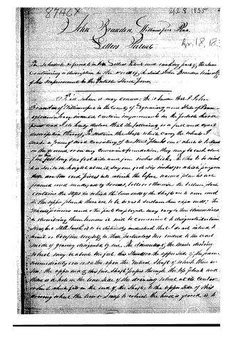
The schedule referred to in the Sellers Patent now making part of the same containing a description in the words of the said John Brandon himself, of his improvement in the Portable Horse Fence.
To all whom it may concern: Be it known that I, John Brandon of Williamsport in the County of Lycoming, one State of Pennsylvania, have invented certain improvements in the portable horse fence and I do hereby declare that the following is a full and exact description thereof, to sustain the rights which I claim. I make a frame of wood consisting of two stout planks one of which is to have in the ground, or on any convenient foundation, they may be each about five feet long one foot wide and four inches thick. Another to be said to be six feet in height above it, say one foot six inches for which purpose there are two end pieces into which the before named planks are framed and made fast by screws, bolts or otherwise; the bottom plank contains the steps in which the lower ends of the shafts are to come and in the upper plank there are to be boxes to sustain their upper ends; the wheels, pins and other parts employed may vary in their dimensions in describing them however it will be convenient to designate certain sizes, but still I wish it to be distinctly understood that I do not intend to limit or confine myself to these particulars nor indeed to the exact mode of gearing designated by me. The diameter of the main driving wheel may be about two feet, this stands on the upper side of the frame immediately over or rather upon the vertical shaft of which there are two; the upper end of this first shaft passes through the top plank and there is a hole in the lower side of the driving wheel at its center or hub which fits on the end of the shaft, to the upper side of this driving wheel the lower shaft to which the horse is geared, is to
Page 3.
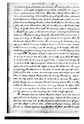
be fastened by any suitable contrivance. In driving wheel gears, a pinion on the upper end of the second shaft, which pinion may be about eight inches in diameter. Upon this second shaft there is to be a second driving wheel which may be of the same diameter with the first in which case it will mesh into a pinion on the first named shaft of the same size with that on the second shaft. Upon the first shaft below the pinion there is a bevel wheel which may be of the same size with the driving wheel, this gears in a bevel pinion upon a horizontal shaft running in suitable bearings below it. This pinion may be of the size of the other pinions but is very according to the space with which it is required that the horizontal shaft shall move. The other end of the horizontal may carry a wheel to receive a strap or band or be connected with an other convenient way with the machinery to be driven. All the wheels and pinions may be of cast iron and the shafts of cast iron wrought for the purpose of perfect adjustment so that the teeth may be made to mesh into each other correctly and that the degree in which they do so may be regulated. I adopt regulating keys or wedges to the step boxes of the shafts and also to the boxes in the upper plank in which the upper ends of the shafts run. The means of adjusting the step boxes a mention is made through the lower plank from side to side immediately under each shaft and into these a wedge shaped key is fitted by driving this key one way or other the step which rests upon it is raised or lowered. The upper end of the shafts run in divided boxes to each of which there is a key fitted in like manner. Nuts ties running through the upper limbs once by means of these the shafts may be moved nearer together or further apart, once the mesh of the teeth nicely adjusted.
The divided boxes in which the first shaft runs, rise above the upper plank so as to form a bearing upon which the hub of the driving wheel rests, and by this means it is prevented from pressing upon the shaft or wheel below. I found the first driving wheel's pinion in which it gears, may be below the plate. Suitable arrangements
Page 4.
8746X
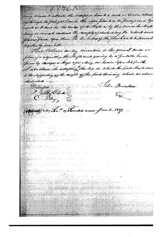
being made to attach the shafts or bars to a rack or collar extending up through the plate, or to make the upper plank in two pieces joined together so as to meet in the center of the shaft, as by this means the shaft may be removed without the necessity of disturbing the wheels and pins fixed upon them. The two halves of the plank are to be secured together by iron bolts.
That I claim as my invention is the general mode or plan for adjusting the shaft and gearing in a portable horse power by means or keys, operating as herein before set forth. I also claim the adapting the key in which the first shaft runs to the supporting of the weight of the first driving wheel, as above described.
Witnesses
John Brandon
Philip Clark
C. Riley
(994464) No. 2, Recorded anew June 1, 1837.
Published accounts: journal notice
Notice in the monthly list of patents
Journal of the Franklin Institute, new ser., vol. 15 (1835), p. 435 · View the page
199. Horse power. John Brandon, Williamsport, Pa.
Published accounts: journal notice
Notice in the monthly list of patents, with remarks
Journal of the Franklin Institute, new ser., vol. 16 (1835), p. 317 · View the page
29. For a Horse Power; John Brandon, Williamsport, Lycoming county, Pennsylvania, April 8.
Remarks. This, like No. 24, is a horse power in which the animal walks round, and turns a shaft by means of a lever; the things claimed are mere matters of arrangement, and consist in "the plan for adjusting the shafts and gearing in a portable horse power, by wedges, or keys; and the adapting of the bore in which the first shaft runs to the sustaining of the weight of the first driving wheel, as described."
About this record
- Patentee
- DATAMP
- Date
- the Name and Date index of patents, DATAMP, USPTO records
- Invention
- DATAMP
- Listed in
- the Name and Date index of patents, DATAMP, USPTO records, Jim Shaw's X-patent list, the Journal of the Franklin Institute, Burke's List of Patents (1847)
- Burke's 1847 Patent Office list gives the same patent.