

Drawings and documents
USPTO scan
The patent as scanned by the USPTO
-
 Page 1
-
 Page 2
-
 Page 3
-
 Page 4


U.S. Patent and Trademark Office · Google Patents
Show the transcription Hide (1,098 words)
Machine transcription (LightOnOCR) of the pages as scanned by the USPTO, most of them the handwritten copies made when the records were restored after the 1836 fire. Not checked; it can misread handwriting, so compare it with the scan.
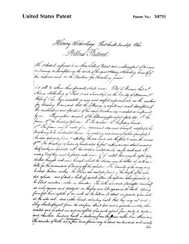
Page 2.
United States Patent
Patent No.: X8751
Henry Heberling, Short Creek Township, Ohio
Letters Patent
The schedule referred to in these Letters Patent and making part of the same containing a description in the words of the said Henry Heberling himself of his improvement in the Machine for threshing grain.
It is all to whom these presents shall come. Be it known that I Henry Heberling of Short Creek Township in the County of Harrison State of Ohio have invented a new and useful improvement in the machine for threshing grain, and that the following is a full and exact description of the constitution and operation of the said Machine as invented or improved by me. The machine consists of the following principal parts viz. 1st The frame. 2nd The threshing cylinder. 3rd The concave. 4th The feeding board.
1st The frame may be made of any convenient size and strength adapted to the Machinery to be constructed thereon. By mortising and tenoning together four posts to the side and end pieces, & rabbeting the side boards, into the posts to receive the concave.
2nd The threshing cylinder is constructed by first making an axis about one and a half inches in diameter with two wood or metal heads, one for each end. If made of wood they must be plated with iron. If of metal there may be eight holes drilled through each rim through which the staves may be bolted on with iron bolts for the convenience of turning off the cylinder. The diameter of the rings may be about thirteen inches. The staves are next to be faced of the length of the intended cylinder, and of such a thickness as will allow the cylinder when finished to be about nineteen inches in diameter. The teeth are made of wrought iron half an inch square and swedged on the face and left square on the back, tapering from full three eighths of an inch at the bottom to about one quarter of an inch at the outer end, and rather broad extending back that they may not bend. They should project from the surface about two and a quarter inches when mounted and be about one and one eighth of an inch apart from center to center, and clamped, bending back or declining from the grain rather than otherwise. The number of teeth in a five horse power may be about one hundred and ninety two.
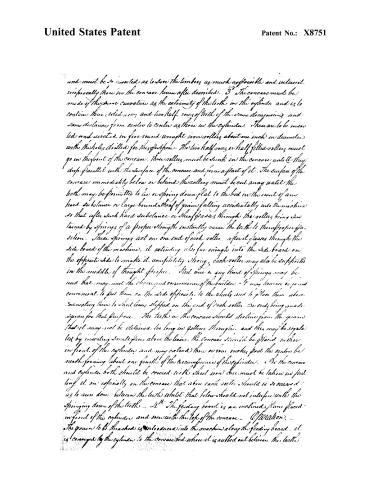
Page 3.
United States Patent
Patent No.: X8751
and must be so inserted as to force the timbers as much as possible and interior reciprocally those in the concave herein after described. 3° The concave must be made of the same curvature as the extremity of the teeth in the cylinder and is to contain three solid 1/2" and two half rows of teeth of the same dimensions and same distance from center to center as those in the cylinder. These are to be inserted and secured in five round wrought iron rollers about one inch in diameter with the holes drilled for the fastenings. The two half rows or half filled rollers must go in the front of the concave. These rollers must be sunk in the concave until they drop parallel with the surface of the concave and form a part of it. The surface of the concave immediately below or behind the rollers must be cut away until the teeth may be permitted to lie or spring down flat to the bed in the event of any hard substance or large bound sheaf of grain falling accidentally into the machine so that after such hard substance or sheaf passes through the rollers being sustained by springs of a proper strength instantly raise the teeth to their proper position. These springs act on one end of each roller, after it passes through the side board of the machine, it extending also far enough into the side board on the opposite side to make it completely strong. Each roller may also be supported in the middle if thought proper. Steel wire or any kind of springs may be used that may meet the choice and convenience of the builder. It may however be found convenient to put them on the side opposite to the wheels and to place them above connecting them to short levers slipped on the end of each roller, the ends being made square for that purpose. The teeth in the concave should decline from the ground that it may not be detained too long in getting through, and this may be regulated by inserting small pins above the levers. The concave should be placed rather in front of the cylinder and may extend there on four inches past the center bed making forming about one fourth of the circumference of the cylinder. 4° The concave and cylinder both should be crowned with sheet iron care must be taken in putting it on especially on the concave that above each roller should be so carried as to run down between the teeth whilst that below should not interfere with the springing down of the teeth. 5° The feeding board is an inclined plane placed in front of the cylinder and even with the top of the concave. Operation. — The grain to be threshed is introduced into the machine along the feeding board, it is conveyed by the cylinder to the concave bed where it is rubbed out between the teeth
Page 4.
United States Patent
Patent No.: X8751
when grain and Straw both pass out together the Straw remaining completely on top
By means of these Rollers many accidents detrimental to the machine and
dangerous to the Thrasher will be avoided and none of that waste of flour caused by a flexible cylinder (its being continually now or left out of Balance) can
occur. What I claim as my invention and not previously known in the
above described machine is particularly the spring Rollers and their application to
a concave for threshing grain — For testimony that the above is a full and clear
act description of the construction and mode of operation of my improvement as
invented or improved by me I have hereunto set my hand this second day
of April in the year Eighteen hundred and thirty five
Witnesses
Henry Stone
Robert Clarke
Henry Weberling
E. A.
C. H. W.
About this record
- Patentee
- DATAMP
- Date
- the Name and Date index of patents, DATAMP, USPTO records
- Invention
- DATAMP
- Listed in
- the Name and Date index of patents, DATAMP, USPTO records, Jim Shaw's X-patent list, Burke's List of Patents (1847)
- Burke's 1847 Patent Office list gives the same patent.