

Drawings and documents
USPTO scan
The patent as scanned by the USPTO
-
 Page 1
-
 Page 2
-
 Page 3


U.S. Patent and Trademark Office · Google Patents
Show the transcription Hide (747 words)
Machine transcription (LightOnOCR) of the pages as scanned by the USPTO, most of them the handwritten copies made when the records were restored after the 1836 fire. Not checked; it can misread handwriting, so compare it with the scan.
Page 1.
8765X
B. Hinkley,
Anti-Friction Roller.
Patented Apr. 14, 1835.
Fig. 1.
Front view.
Fig. 3.
Fig. 5.
Fig. 4.
Fig. 6.
THE HELIOTYPE PRINTING CO. 220 DEVONSHIRE ST. BOSTON.
Page 2.
7765X April 14, 1835 241
To Benjamin Pinkley of Fayette Maine
Letters Patent.
The Schedule referred to in these Letters Patent and making part of the same containing a description in the words of the said Benjamin Pinkley himself of his improvement in the mode of diminishing friction on the bearings of shafts axles and other machinery.
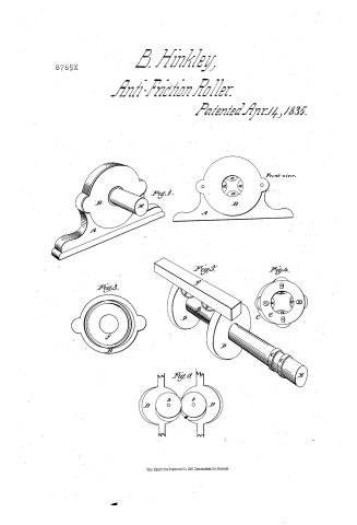
To all to whom these presents shall come. To wit Know that I Benjamin Pinkley of Fayette in the County of Kennebec and State of Maine. Machinist. have invented a new and useful improvement in the mode of diminishing friction on the bearings of axles shafts gudgeons and other machinery and that the following is a full and exact description of the construction and operation of the said machinery as invented and improved by me. Fig One of the specified drawings which constitute a part of this description represents a front view of the Box and rollers without the shaft being inserted. A represents the outside of the box. B represents the outside of the plate making a part of the Box. a a a a represents four small anti-friction rollers running in the box. Fig 1 represents the whole of the box with the shaft inserted. B the plate. A the outside of the Box. Fig 3 represents the inside of the plate 13 of Fig 3 the rim of the plate and f the part of the surface within the projection forming the groove in the box Fig 4 represents the bands and rollers as they are when in the box. C C are the bands intended to keep the rollers in their places formed with ob long holes in which the pivot of the rollers play a a a a represents the rollers. These four first described figures of the drawings constitute what I call the anti-friction box and may be formed of cast iron or any other suitable metal. Fig 5 represents the shaft or axletree with two centre wheels and two anti-friction Rollers playing between the wheels. B represents this shaft. D D two centre wheels upon the shaft. F a small section of the frame work of a carriage or other frame work b b are two anti-friction rollers flying between the two centre wheels in such a manner as to prevent side friction of the rollers inside of the box. E represents the end of the shaft which comes through the hub of the wheel when used on Carriages C C show the projection each side of the groove in the shaft in which the rollers in the Box are intended to run and this groove will be the bearing of the shaft. Fig 6 represents a view of the
Page 3.
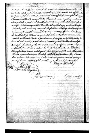
two centre wheels with the anti-friction rollers between them. The two centre wheels with the anti-friction rollers are intended to take off the side friction, and the box rollers are intended to take off the friction of the bearings. These can be applied to carriages, Mules, Steamboats, or in any other machinery where a shaft is used. I do not pretend to do away with all friction upon a shaft, but the arrangement of the rollers taking the bearing on the outer edges of the rollers will materially diminish the friction. Having described my said improvement, and the manner in which it is intended to operate, I do hereby declare that what I claim as new and for which I ask the exclusive use consists in the mode herein before described of applying anti-friction rollers between the cylinder shaft or other parts of machinery and the Box herein before described. The attaching this Box to a carriage body or frame works. The groove in this shaft or axle tree and in this box to keep the rollers and shaft in their respective places so as to prevent the interference with each other's motion. The two centre wheels upon the shaft with the anti-friction rollers between them as herein before described to diminish side friction and the arrangement of the several parts of the machinery as herein before described.
Benjamin Hinkley
Testd. Webster
Mfd. John Oles
Mr. M. Vaughan
(Drawing.) (750 words)
Published accounts: journal notice
Notice in the monthly list of patents
Journal of the Franklin Institute, new ser., vol. 15 (1835), p. 435 · View the page
220. Friction, diminishing.-P. Hinkley, Kennebec county, Maine,
Published accounts: journal notice
Notice in the monthly list of patents
Journal of the Franklin Institute, new ser., vol. 16 (1835), p. 323 · View the page
50. For Machinery for Diminishing Friction; Benjamin Hinkley, Fayette, Kennebec county, Maine, April 14.
About this record
- Patentee
- DATAMP
- Date
- the Name and Date index of patents, DATAMP, USPTO records
- Invention
- DATAMP
- Listed in
- the Name and Date index of patents, DATAMP, USPTO records, Jim Shaw's X-patent list, the Journal of the Franklin Institute, Burke's List of Patents (1847)
- Burke's 1847 Patent Office list gives the same patent.